
Professional PCB manufacturing and assembly
Building 6, Zone 3, Yuekang Road,Bao'an District, Shenzhen, China
+86-13410863085Mon.-Sat.08:00-20:00

The first thing you do when you get a PCB is to check it. Why?
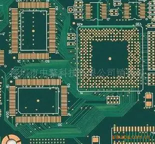
Whether it is a board made by others or a PCB designed and manufactured by yourself, the first thing you need to do is to check the integrity of the board, such as tin plating, cracks, short circuit, open circuit, drilling and other problems. If the role of the board is more rigorous, you can check the resistance between the power supply and the ground wire.
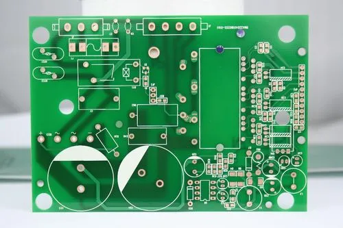
Generally, the components will be installed on the self-made board after the tin plating is completed. If someone can do it, it is just an empty shell of a tinned PCB with holes. When you need to get it, you can install the components yourself.
Some people have a lot of information about PCB boards designed by themselves, so they like to test all the components at once. In fa PCB componentct, it is recommended to do it bit by bit.
The debugging of new PCB can start from the power supply. The safest way is to install a fuse and then connect the power supply (in case, it is better to use a regulated power supply).
Use the regulated power supply to set the overcurrent protection current, and then slowly adjust the voltage of the regulated power supply upwards. In this process, it is necessary to monitor the input current, input voltage and output voltage of the board.
When the voltage is increased upward, no over-current protection occurs and the output voltage is normal, which means that the power supply of the board is OK. If the output voltage or over-current protection exceeds the normal value, the cause of the fault must be investigated.
installation
During the debugging process, the modules are gradually installed. Each module or several modules are tested according to the above steps, which is conducive to avoiding some hidden errors at the beginning of the design, or errors in the installation of components, leading to overcurrent burning of components.
In case of failure during installation, the following methods are generally used for troubleshooting:
Troubleshooting method I: voltage measurement method
In case of over-current protection, do not disassemble the components in a hurry. First confirm the voltage of the power supply pin of each PCB chip to see if it is within the normal range. Then check the reference voltage and working voltage in turn.
For example, when the silicon triode is turned on, the voltage of the BE junction will be about 0.7V, and that of the CE junction will generally be 0.3V or less
When the BE junction voltage is found to be higher than 0.7V during the test (special triodes such as Darlington are excluded here), it is possible that the BE junction is open circuit. The fault can be eliminated by checking the voltage at each point in turn.
Fault troubleshooting method II: signal injection method
The signal injection method is more troublesome than measuring the voltage. When transmitting the signal source to the input terminal, we need to measure the waveform of each subsequent point in order to find the fault point from the waveform.
Of course, you can also use tweezers to detect the input end by touching the input end with tweezers and then observing the response of the input end. Generally, this method is used in the case of audio and video amplification circuits (Note: never use this method in hot floor circuits and high-voltage circuits, which is prone to electric shock accidents).
This method detects that the previous stage is normal, and the latter stage responds, so the fault is not in the next stage, but in the previous stage.
Troubleshooting method 3: Others
PCB appearance detector
The above two methods are relatively simple and direct. In addition, the common methods of seeing, smelling, listening and touching are those that require experienced engineers to detect problems.
Generally, "look" is not to see the status of the testing instrument, but to see whether the appearance of the components is complete; "Smell" mainly refers to whether the smell of components is abnormal, such as burning smell, electrolyte and other smells. Generally, components will give off an unpleasant burning smell when they are damaged.
And "listening" is mainly to listen to whether the sound of the board is normal under the working condition; As for "touching", it is not to feel whether the PCB components are loose, but to feel whether the component temperature is normal with your hands. For example, under working conditions, the cold components are hot, while the hot components are extremely cold. Do not directly pinch with your hands during the touch process to prevent the hands from being scalded by high temperature.


Just upload Gerber files, BOM files and design files, and the KINGFORD team will provide a complete quotation within 24h.