
Professional PCB manufacturing and assembly
Building 6, Zone 3, Yuekang Road,Bao'an District, Shenzhen, China
+86-13410863085Mon.-Sat.08:00-20:00

Details of SMT process solutions for small factories
SMT process: short for Surface Mount Technology, SMT surface mount technology is an electronic assembly technology that originated in the 1960s, was initially developed by IBM in the United States, and then gradually matured in the late 1980s. SMT technology is to install electronic components, such as resistors, capacitors, transistors, integrated circuits, etc. on printed circuit boards, and form electrical connections through lead soldering. The components used are also referred to as SMD (surface mount devices). The biggest difference between SMT and plug-in technology is that SMT surface adhesion technology does not need to reserve corresponding through holes for the pins of components, and the component size of surface adhesion technology is much smaller than that of plug-in packaging. This SMT technology can greatly reduce the volume of electronic products to achieve the purpose of thin and short, referred to as SMT process.
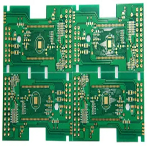
Now the PCB size is 10 × 15cm, including a total of 38 0805 and 1206 pieces and a patch IC. The patch scheme is set based on 20 plug-in modules as THT process. The following scheme is preliminarily set with the daily output of 5K as the production quantity. Electronic manufacturers complete the production and assembly of a complete set of electronic products, which are generally composed of SMT chip processing process and traditional THT plug-in process. It is recommended that SMT process be combined with traditional THT process for production at this stage.
1、 SMT production process suggestions for small factories
1. Recommended assembly method:
1) Single side solder paste welding: Note: Single side welding and double side welding are basically the same in production process, so the process selection and equipment configuration are basically the same in terms of personnel ranking. In actual production operations, side A is welded first, and then the same process is repeated. The setting of tin printing process and reflow soldering machine is adjusted relatively to weld side B.
2、 SMT device configuration
A. Tin printing part:
1) 1 manual printing machine
2) 1 scraper (tin paste mixing knife)
3) Steel mesh (customized according to your products)
4) . Tin paste (patch adhesive)
Note: In case of double-sided welding, the positioning plate shall be added on the printing machine, and the solder paste with the same melting point can be used.
B. Patch part:
1) 10 manual tip pens
The speed of manual patch is generally 1/2-3 seconds per person, and the mainland can be designed to place a component within 3 seconds.
2) 20 material racks
3) 1 platform production line
Since it is possible to weld on both sides, there must be a guide rail.
Note: One full-automatic mounting machine (0.20 seconds/piece) can be selected for the mounting part
C. Welding part:
1) 1 set of hot air reflow welding machine
3、 SMT process flow
Start --->Solder paste printed on side A --->SMD components mounted on side A --->Component position alignment QC --->Reflow soldering machine welding --->Appearance inspection and repair QC --->B-side in-line components --->B-side welding T-HT components --->Appearance inspection and repair QC --->


Just upload Gerber files, BOM files and design files, and the KINGFORD team will provide a complete quotation within 24h.