
Professional PCB manufacturing and assembly
Building 6, Zone 3, Yuekang Road,Bao'an District, Shenzhen, China
+86-13410863085Mon.-Sat.08:00-20:00

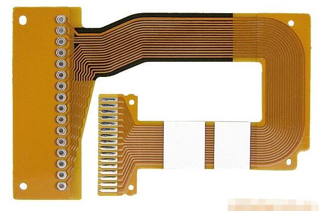
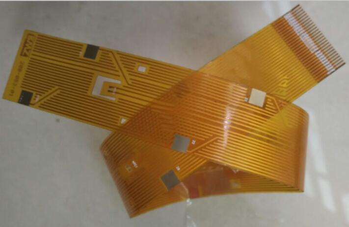
FPC flexible printed circuit board, called Flexible Printed Circuit in English, is also called flexible circuit board, which is a highly reliable and excellent flexible printed circuit made of flexible insulating substrates such as polyimide or polyester film. It has the characteristics of high wiring density, light weight, thin thickness and good bending performance. Flexible printed circuit board can also be divided into single-sided, double-sided and multilayer boards.
Fpc flexible circuit board testing methods and standards

FPC is mainly used in the connection parts of electronic products. The advantage is that all lines are configured. Eliminate the connection workers of redundant cables; It can improve the softness. Strengthen the assembly of three-dimensional space in the limited space; It can effectively reduce the product volume. Increase the convenience of carrying; It also reduces the weight of the final product.
Test scope
The scope of this standard includes single-sided, double-sided and multilayer pcb boards of flexible circuits. The flexible circuit board mentioned in this standard refers to single, double and multi-layer flexible copper foil substrates with polyimide (PI) or polyester (PET) as the substrate, including adhesive (3L-FCCL) and adhesive (2L-FCCL) flexible copper foil substrates.
Test purpose
The purpose of this standard is to establish a general rule for the identification of the appearance quality of flexible circuit boards, as the basis for the identification of the appearance quality of flexible board products between Tianpai Company and suppliers, which is helpful to improve pcb manufacturing technology and reduce resource waste and environmental pollution caused by unnecessary scrapping.
test method
The test methods described in this specification mainly use visual inspection, magnifying glass and ruler as the main inspection methods and tools. If necessary, other applicable test instruments or equipment can be used for inspection.
Basic test standards
1. Appearance of substrate film surface:
The allowable defect range of substrate film surface appearance without conductor is listed in the table. It is not allowed to have other bumps, creases, wrinkles and foreign matters that affect the use.
2. Overlay appearance:
Defects of covering film and coating appearance: allowable range, no concave convex, crease, wrinkle, delamination, etc. affecting the use.
3. Deviation between connecting disc and covering layer:
The allowable deviation e of the connecting disc and the covering layer is less than ± 0.3 mm when the overall dimension is less than 100 mm, and less than ± 0.3% when the overall dimension is more than 100 mm.
4. Flow penetration of binder and coating:
The flow permeability f of the binder and the covering coating shall be less than 0.2mm. However, the minimum ring width g ≥ 0.05mm must be met at the connecting plate plus the covering layer deviation and punching deviation
5. Discoloration:
Discoloration of the conductor under the coating must still meet the requirements of voltage resistance, bending resistance, bending resistance and welding resistance after 96 hours of humidity resistance test at 40 ℃ and 90% humidity.
6. Holiday of coating:
The missed coating of the coating layer shall be tested according to the solderability requirements. The conductor of the missed coating part of the coating layer shall not be pasted with tin.
7. Poor electroplating combination:
Layering is not allowed for the coating. The width of the coating where the coating is poorly bonded is W1, the length is L, and the width of the conductor after processing is W, and the poor coating bonding shall not damage the reliability of the contact area.
The above are the test methods and standards for fpc flexible circuit boards compiled by me. I hope they can help you
What are the four common FPC FPC processes
Oct 26,2022


Just upload Gerber files, BOM files and design files, and the KINGFORD team will provide a complete quotation within 24h.