
Professional PCB manufacturing and assembly
Building 6, Zone 3, Yuekang Road,Bao'an District, Shenzhen, China
+86-13410863085Mon.-Sat.08:00-20:00

Component Positioning Principles in PCB Design
1 The PCB design should be carried out in a certain order, such as from left to right and from top to bottom
2. The width and line spacing of the terminal strip shall be moderate, and the spacing between the two pads of the capacitor shall be consistent with the spacing between the capacitor leads as far as possible.
3. When designing the wiring diagram, the wiring shall be as few as possible and the lines shall be simple and clear.
4. When designing the wiring diagram, pay attention to the arrangement order of pins and the reasonable spacing between components.
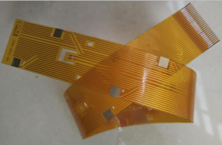
Circuit board

5. Wiring direction:
From the welding surface, the layout of component bearings should be consistent with the schematic diagram as much as possible, and the wiring direction should be consistent with the circuit diagram. Because various parameters of the welding surface are often required to be tested during the production process, production inspection, debugging and maintenance should be done well (Note: it refers to the premise of circuit efficiency and machine installation and panel layout requirements).
6. On the premise of ensuring the circuit efficiency requirements, the design shall strive for reasonable wiring, minimize the use of external connections across lines, and conduct wiring according to certain charging requirements, which is intuitive and easy to install, height and maintain.
7. The layout and distribution of each component shall be reasonable and uniform, and strive to be neat, beautiful and rigorous in structure.
8. Layout direction of inlet and outlet terminals
(1) The distance between these two leads and the end is not too large, generally 2-3/10 inches.
(2) Incoming and outgoing lines shall be concentrated on 1 to 2 sides as much as possible, and shall not be too discrete.
9 Potentiometer: IC seat placement principle
(1) Potentiometer: it is used to adjust the output voltage of the voltage regulator. The designed potentiometer shall fully adjust the output voltage rise in the clockwise direction and the output voltage of the voltage regulator section decreases in the counterclockwise direction; In the adjustable constant current charger, the potentiometer is used to adjust the multiple size of the charging current. When designing the potentiometer, it should be fully adjusted clockwise to increase the current. The potentiometer shall be placed at a position that meets the requirements of the whole machine structure installation and panel layout. It shall be placed at the edge of the plate as far as possible, and the handle shall be rotated outward.
(2) IC base: When designing printed boards, when using IC base, special attention must be paid to whether the location of the positioning slot on the IC base is correct, and whether the location of each IC pin is correct. For example, the first foot can only be located at the lower right corner line or upper left corner of the IC base, and close to the positioning slot (from the welding surface).
10. Position direction of resistor and diode in PCB layout:
PCB design is divided into two types: horizontal and vertical:
(1) Flat: When the number of circuit components is small and the size of the circuit board is large, it is generally best to use flat; For flat resistance less than 1/4W, the distance between two pads is usually 4/10 inch, for flat resistance of 1/2W, the distance between two pads is usually 5/10 inch; Flat diode, 1N400X series rectifier, generally 3/10 inch; 1N540X series rectifier tube, generally 4-5/10 inches.
(2) Vertical: When the number of circuit components is large and the size of the circuit board is small, the general PCB design is vertical. When the distance between two pads is 1-2/10 inches, vertical
The above is the explanation given by the editor of pcb circuit board company.
If you want to know more about PCBA, you can go to our company's home page to learn about it.
In addition, our company also sells various circuit boards,
High frequency circuit board and SMT chip are waiting for your presence again.
How are components of PCB connected?
Oct 23,2022


Just upload Gerber files, BOM files and design files, and the KINGFORD team will provide a complete quotation within 24h.