
Professional PCB manufacturing and assembly
Building 6, Zone 3, Yuekang Road,Bao'an District, Shenzhen, China
+86-13410863085Mon.-Sat.08:00-20:00

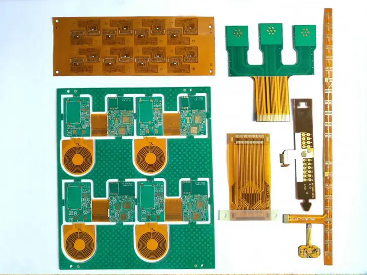
Flexible circuit board (FPC) is a highly reliable and excellent flexible printed circuit board made of polyimide or polyester film. FPC is also known as flexible circuit board and flexible circuit board. It is favored for its excellent characteristics such as light weight, thin thickness, and free bending and folding.

FPC is a technology developed by the United States for the development of aerospace rocket technology in the 1970s. By embedding circuit designs on flexible thin and light plastic sheets, a large number of precision components can be stacked in a narrow and limited space to form a flexible flex circuit. This kind of circuit can be bent and folded at will, light weight, small size, good heat dissipation, convenient installation, breaking through the traditional interconnection technology. In the structure of the flexible circuit, the constituent materials are insulating films, conductors and adhesives.
Constituent material
insulating film
The insulating film forms the base layer of the circuit, and the adhesive bonds the copper foil to the insulating layer. In multi-layer designs, it is then bonded to the inner layer. They are also used as a protective covering to insulate circuits from dust and moisture, and to reduce stress during flexing, the copper foil forms a conductive layer.
In some flexible circuits, rigid members formed of aluminum or stainless steel are used, which can provide dimensional stability, physical support for the placement of components and wires, and stress relief. The adhesive bonds the rigid member and the flexible circuit together. Another material that is sometimes used in flexible circuits is an adhesive layer, which is formed by coating an adhesive on both sides of an insulating film. Adhesive plies provide environmental protection and electrical insulation, as well as the ability to eliminate a single film, as well as the ability to bond multiple layers with fewer layers.
conductor
Copper foil is suitable for use in flexible circuits, it can be electrodeposited (ED), or plated. The electrodeposited copper foil has a glossy surface on one side, while the processed surface on the other side is dull. It is a flexible material that can be made in many thicknesses and widths, and the matte side of ED copper foil is often specially treated to improve its adhesion. In addition to flexibility, wrought copper foil also has the characteristics of hardness and smoothness, which is suitable for applications requiring dynamic deflection.
glue
In addition to being used to bond insulating films to conductive materials, adhesives can also be used as overlays, as protective coatings, and as overlay coatings. The main difference between the two is the application used, the cover layer bonding the cover insulating film to form the circuit of the laminated construction. Overlay coating of adhesive using screen printing technique.

Not all laminate structures contain adhesives, and laminates without adhesives result in thinner circuits and greater flexibility. It has better thermal conductivity than adhesive-based laminate constructions. Due to the thin structure of the adhesiveless flex circuit and the improved thermal conductivity due to the elimination of the thermal resistance of the adhesive, it can be used in working environments where the flex circuit based on the adhesive laminate structure cannot be used. .
basic structure
Copper foil substrate: Copper Film.
Copper foil: It is basically divided into two types: electrolytic copper and rolled copper. Common thicknesses are 1oz, 1/2oz and 1/3oz.
Substrate film: Common thicknesses are 1mil and 1/2mil.
Glue: Adhesive, the thickness is determined according to customer requirements.
Cover film protective film: Cover Film, used for surface insulation, the common thickness is 1mil and 1/2mil.
Release paper: avoid the adhesive from sticking to foreign matter before pressing, which is convenient for operation.
Reinforcing board: PI Stiffener Film, which reinforces the mechanical strength of FPC and facilitates surface mounting operations. Common thicknesses range from 3 mil to 9 mil.
EMI: Electromagnetic shielding film to protect the circuit inside the circuit board from interference from the outside world (strong electromagnetic area or susceptible area).
How to Solder
Steps
(1) Before soldering, apply flux on the pad and treat it with a soldering iron to prevent the pad from being poorly tinned or oxidized, resulting in poor soldering, and the chip generally does not need to be processed.
(2) Carefully place the PQFP chip on the PCB with tweezers, taking care not to damage the pins. Align it with the pads, making sure the chip is placed in the correct orientation. Adjust the temperature of the soldering iron to more than 300 degrees Celsius, dip a small amount of solder on the tip of the soldering iron, press down on the chip that has been aligned with the tool, and add a small amount of flux to the pins at the two opposite corners. Hold the chip down and solder the pins on two opposite corners so that the chip is fixed and cannot be moved. Recheck the alignment of the chip after soldering the diagonal corners. Adjust if necessary or remove and realign on the PCB.
(3) When starting to solder all the pins, you should add solder to the tip of the soldering iron and apply flux to all the pins to keep the pins wet. Touch the end of each pin of the chip with the tip of the soldering iron until you see solder flowing into the pin. When soldering, keep the tip of the soldering iron parallel to the pins to be soldered to prevent overlapping due to excess solder.
(4) After soldering all pins, wet all pins with flux to clean the solder. Absorb excess solder where needed to eliminate any shorts and laps. Finally, use tweezers to check whether there is any virtual soldering. After the inspection is completed, remove the flux from the circuit board, dip a stiff brush in alcohol and wipe it carefully along the direction of the pins until the flux disappears.
(5) SMD RC components are relatively easy to solder. You can put tin on a solder joint first, then put one end of the component, clamp the component with tweezers, and after soldering one end, check whether it is placed correctly. ;If it has been placed, then solder the other end.
Precautions
In terms of layout, when the size of the circuit board is too large, although the soldering is easier to control, the printed lines are long, the impedance increases, the anti-noise ability decreases, and the cost increases; if it is too small, the heat dissipation decreases, the soldering is difficult to control, and adjacent lines are prone to appear. Mutual interference, such as electromagnetic interference of circuit boards, etc.

Therefore, the PCB board design must be optimized:
Shorten the connection between high-frequency components and reduce EMI interference.
Components with heavy weight (such as more than 20g) should be fixed with brackets and then welded.
The heating element should consider the heat dissipation problem to prevent defects and rework caused by large ΔT on the surface of the element, and the thermal element should be kept away from the heat source.
The arrangement of components should be as parallel as possible, which is not only beautiful but also easy to weld, and suitable for mass production. The board is designed as a 4:3 rectangle.
Do not change the wire width abruptly to avoid wiring discontinuities.
When the pcb circuit board is heated for a long time, the copper foil is easy to expand and fall off. Therefore, the use of large-area copper foil should be avoided.


Just upload Gerber files, BOM files and design files, and the KINGFORD team will provide a complete quotation within 24h.