
Professional PCB manufacturing and assembly
Building 6, Zone 3, Yuekang Road,Bao'an District, Shenzhen, China
+86-13410863085Mon.-Sat.08:00-20:00

Circuit boardsplay an important role in the electronics industry. This is because they are widely used in a variety of roles in devices such as computers, televisions and power systems. A printed circuit board consists of electrically conductive tracks that interconnect components on the board. They are also commonly used for electrical safety testing or verification.
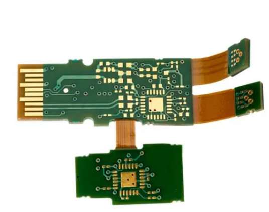
According to JIS C5017, the Japanese industry standard for measuring the mechanical properties of printed circuit boards, a flexible printed circuit board (FPC) is a PCB with a cylindrical or rectangular shape that can be changed in size according to the requirements of its application. The standard divides FPCS into two categories: rigid and flexible. Rigid FPC helps to mechanically connect parts, but cannot bend. Flexible FPC is a double-sided PCB that can withstand bending forces. In addition, we mainly use it for electrical interconnection applications.
The FPC is popular with engineers because it is easy to modify and customize without any solder joints. The flexibility of the FPC allows for different retrofit solutions. It significantly reduces the cost of printing new plates for specific applications. For example, adding functionality to the surface of an existing circuit board is easier than creating an entirely new board from scratch.
The composition of FPC materials depends on their intended application and end use. FPC's flexibility depends on the material's ability to resist cracking, warping, and mechanical damage while maintaining high electrical conductivity. Therefore, manufacturers tend to manufacture FPC flexible printed circuits using fiberglass or FR-4 materials. It consists of a mixture of epoxy resin and glass fibers. The FR-4 is a rigid plate that combines thermal and electrical properties.
1. Insulation film
It is a layer of high-density polyethylene made by squeezing out the resin through a nozzle and coating it on a substrate. HDPE films eliminate capacitive coupling between substrates. It also eliminates other circuits to electrically shield the interconnection at the top of the board. The HDPE layer also acts as a vapor barrier to prevent moisture from entering the circuit during curing.
2. Electrostatic bonding layer
After the HDPE film is applied, the adhesive layer can connect the components. These components may include potentiometers and leds on the circuit board to improve performance or reduce cost. The bonding layer is acrylic or polyimide, allowing the LED to bond directly to the FPC, saving material and assembly time.
Step 3: Conductor
Then we add a conductive layer on top of the adhesive layer. The layer can be polyimide or epoxy resin or the printed circuit board itself. To avoid warping, we can apply a conductor to a solution at 100 °C.
4. Reinforcement board
Finally, we added a second bonding layer to the conductor to further reduce bending or cracking problems. We usually use cellulose or acrylic to make this layer.
To make an FPC circuit board, the components are first pre-assembled onto the board and then cut to size. The FPC material is then placed into the mold and bent without breaking. Normally, we heat the FPC material to 120 °C for approximately 1 hour. This is done to obtain the necessary stiffness so that the material can resist flexors and bend easily. The component is then added to the die and pressurized to embed it in the FPC.
Next, we coat the top of the assembly with conductive ink. It helps create a smooth surface, prevents resistance and improves performance.
5. Overlay
The covering is the top plate made of polyimide or acrylic. The overlay protects the underside of the FPC material. It also acts as insulation, preventing moisture from entering the FPC material. The mulch also has high temperature resistance, allowing us to use it in ovens and heaters.
Why do you need to use FPC boards
We use FPCS in applications that require flexibility and conductivity. But when we need mechanical strength, we don't use it. Because FPCS are thin and light, we use them in portable devices such as cell phones, digital cameras and walkie-talkies. We can use them in large devices like peripherals and power supplies.
1. Reduce weight and space
Since FPCS do not have terminals for electrical connectors, they can be used in devices that require light weight but require the output of many components to be connected. For example, portable GPS devices can use FPCS to connect small batteries to the mainframe. The console has an internal rechargeable battery. However, the GPS receiver also needs a power supply and some other features, such as a display and buttons. The FPC provides all of these components and connects them together.
2. Easy customization
FPCS are flexible and we can cut them to the size we want. Since they are not welded, they can be easily removed from the circuit board and modified for new uses. You can make entirely new electronics by adding FPCS with add-ons to boards already used for other purposes. For example, we can add FPCS to connect external batteries to existing products. They include a car radio that adds to its functionality without completely replacing it.
3. Meet dynamic bending requirements
We mainly use FPCS on portable devices because of their flexibility and light weight. They can be adapted to flexible products such as mobile phones, or cut to the size needed for new circuit boards. These characteristics make them ideal for use in consumer electronics.

4. Bend to facilitate installation and maintenance
We use FPCS in solar panels, satellites, generators and electric vehicles in homes and buildings. People can easily install solar panels in places where roofs cannot be built or views are difficult. The flexibility of these FPCS means they can be adapted to many different environments while still providing electrical pathways between the various components. We also use FPC in electric cars. This is because they have a lightweight construction while maintaining the required strength to ensure they do not break when driven.
5. Impedance control
Manufacturers use high quality materials to make FPCS and have high electrical conductivity. Therefore, we also use them in consumer electronics where impedance control is required. The main advantage of using FPC instead of a welded connection is that we can easily control the impedance, which is necessary for mobile devices such as cell phones.
6. Scalability
We will need to expand some electronic devices such as solar panels or electric cars. This is due to technological advances or improved user needs. These products can use FPC to connect to a variety of other components that we can add later when new features are needed.
7. Improve reliability and repeatability
When we use an FPC in a solar panel, we weigh and mechanically test the FPC to maintain stability after installation. This process ensures reliable and smooth operation of the product in many different environments.
8. Thermal management
We can design products using FPC with good thermal management. Since we can't solder the FPC to the motherboard, we can move it and replace it with another one to change its thermal properties. This process ensures that the product is always running well.
9. Enhance your beauty
We can design the FPC to be very thin to reduce the size of the final product and make it look very nice. By printing components on thin films rather than inside the FPC, one can achieve this goal. The manufacturer prints the components on top of the FPC. It still seems connected to it, while retaining its function and appearance.
10. Remove the connector
FPCS require no connectors because they can be easily removed and reconnected to other boards. Since there are no connectors and terminals, you do not need to disassemble the product each time you access the cable. You can then reconnect the FPC later, reducing production costs and ensuring that the product looks clean.
11. Reduce assembly costs
In many cases, FPCS can reduce assembly costs. For example, a semiconductor company needs to add new components to its production line. We can use the FPC with other components to create a circuit board. This increases the functionality of the product while reducing the cost of production.
12. Increase scalability
The FPC can connect many components to the central board to create larger devices. Because they are flexible and lightweight, we can assemble these boards into large products with high performance features.
13. Provide uniform electrical characteristics for high speed circuits
Because companies manufacture FPCS using the same high-quality materials and techniques as fiber optics, they provide reliable electrical characteristics for high-speed circuits. As a result, these circuits can operate at very high speeds without becoming unstable.
14. Improve signal integrity
We can design FPCS to improve signal integrity by reducing noise and reflection. They also enhance transmission performance and electromagnetic interference (EMI) resistance.
Flexible circuit option
The text above indicates that the FPC is ideal for a variety of applications. In addition, we can replace the traditional circuit board. The polyester (PET) and polyimide (PEEK) materials used in FPC are conductive. Therefore, they can be connected to other circuits and components. They also provide mechanical protection for sturdier products. The 1-ounce thick Type-V-PET substrate used in the FPC is flexible and can carry large amounts of current. It can also withstand high temperatures. This makes it ideal for high power applications such as solar panels.
First layer
We form a "graph overlay" at this stage. The surface is first cleaned, the screen is printed, and then cured to ensure a high quality printing process with repeatable properties. Level 1 is where most of the changes are made. We print screen printing or other overlay patterns. We usually do this in CMYK format, using a high quality inkjet printer to ensure the clearest possible image.
Second layer
The laminating phase includes the addition of trace lines. This layer is a conductive adhesive that is pressed with the first layer to form the final FPC product. Adhesives must provide a smooth surface to achieve electrical and mechanical stability. This can be achieved by vacuum or pressure laminating, depending on the rigidity or flexibility of the final product.
The third layer
This is an essential layer because it provides a strong mechanical bond between the first and second layers. One of the most popular adhesive options is a thin ceramic adhesive that provides excellent mechanical properties. We can apply this using manual or automated systems to ensure consistent production quality at each location.
Fourth floor
The final layer determines the physical look and feel of the FPC. The thickness of the layer can vary according to various factors. They include material types, application requirements and production locations.
We use flexible printed circuits (FPCS) in many different applications, such as solar panels, electric cars and aircraft. In addition, we use them in new applications such as aerial drones and wearable electronics. Therefore, the FPC must provide reliable electrical characteristics for high-speed circuits. FPC manufacturers use more than 20 different chip types and a wide range of specialized components to make their final products.
Difference between PET and FPC
PET is the polymer that we commonly use in FPC. PET has low thermal expansibility, and it's also transparent, which means we can use it in solar panels or display panels. The FPC, on the other hand, can be used flexibly for high-performance displays or indoor use.
Flexible printed circuit board (FPC) is a kind of flexible circuit board with low cost and significant saving of transportation space. When we apply PCBS with many components, they grow in size. FPCS are easy to manufacture and construct due to the key characteristics of flexibility.
Flexible printed circuit card (FPC) combines integrated circuit (IC) and film printed circuit trace. We use them to make flexible circuit boards. Flexible printed circuit card is an electronic device used to accommodate integrated circuits (ics).
Flexible printed circuits (FPCS) are thin plastic sheets that we can use in applications. Some examples include new applications such as solar panels, electric cars, airplanes and aerial drones. We make FPCS out of flexible plastics that conduct electricity. A plastic top layer having various circuits and components is etched and printed. This helps create circuits that are thin enough to be flexible and durable.
Flexible printed circuit cards (FPCS) are helpful in many different applications. They include solar panels, electric cars and airplanes. We are also using them in new applications such as aerial drones and wearable electronics. Therefore, the FPC must provide reliable electrical characteristics for high-speed circuits.
Advantage of cable width
One of the great advantages of FPC technology is the maintenance of high line width, which improves performance. This performance improvement is significant for wireless applications. There is a significant difference between the time it takes for a radio signal to travel from one point on the circuit board to another and the time it takes for the signal to be disrupted by noise and interference. Higher line widths allow for greater signal integrity by reducing these delays while increasing the data rate and transmission range.
Another benefit of FPC technology is the low dielectric constant (low εr). PET allows for a smaller trace width and higher performance than other materials such as FR-4. Using low epsilon r in FPC routing also improves signal integrity by reducing line width variation.
Electrical characteristics
The FPC offers a variety of electrical advantages, mainly due to the use of PET. As mentioned earlier, PET is a low dielectric material, and as a result, FPCS using PET can achieve low line-width variations. Reducing linewidth variation can improve noise resistance and signal integrity.
The FPC also allows for easy wiring, which increases manufacturing output. Low temperature co-fired ceramics (LTCC) and silica gel also contribute to the FPC process. It provides enhanced thermal performance to the circuit.
The most common method of FPC manufacturing is transfer printing. That's because it involves transferring e-ink to a surface. Part of the surface is then etched away to create the circuit. Transfer printing allows for very high speed processing power. We may need circuits that support wireless communication, such as WiFi.
Manufacturing technology
FPC manufacturing is a complex process involving the use of many different materials and processes. We can make FPC by transferring ink onto a flexible substrate. This creates the circuit and removes the substrate portion to expose the circuit.a
Application of flexible printed circuit board
Mar 12,2023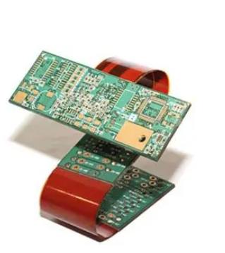


Just upload Gerber files, BOM files and design files, and the KINGFORD team will provide a complete quotation within 24h.