
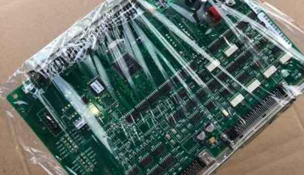
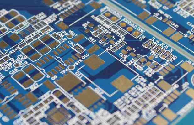
Professional PCB manufacturing and assembly
Building 6, Zone 3, Yuekang Road,Bao'an District, Shenzhen, China
+86-13410863085Mon.-Sat.08:00-20:00

In theory, after the printed circuit enters the etching stage, in the process of processing the printed circuit by the graphic electroplating method, the ideal state should be: the sum of the thickness of the copper and tin or copper and lead tin after electroplating should not exceed the thickness of the electroplating sensitive film, so that the electroplating graphics are completely blocked by the "wall" on both sides of the film and embedded in it. However, in real production, the world's printed circuit boards after electroplating, the coating pattern is much thicker than the sensitive pattern. In the process of electroplating copper and lead tin, because the coating height exceeds the photosensitive film, there is a tendency to lateral accumulation, which results in problems. A tin or lead-tin resist layer covering the top of the line extends to both sides to form a "edge", which covers a small amount of sensitive film under the "edge".
The "edge" formed by tin or lead tin makes it impossible to completely remove the sensitive film when the film is removed, leaving a small part of the "residual glue" below the "edge". The "residual glue" or "residual film" left behind the "edge" of the resist will cause incomplete etching. The lines form "copper roots" on both sides after etching, and the copper roots narrow the line spacing, resulting in the printed board does not meet the requirements of Party A and may even be rejected. The rejection will greatly increase the production cost of PCB.
In addition, in many cases, due to the reaction and the formation of dissolution, in the printed circuit industry, residual film and copper may also form accumulation in the corrosive fluid and blocked in the nozzle of the corrosion machine and the acid pump, have to shut down for treatment and cleaning, and affect the work efficiency.
In printed circuit processing, ammonia etching is a relatively fine and complex chemical reaction process. On the other hand, it is an easy task. Once the process is up-regulated, continuous production can be carried out. The key is to maintain a continuous working state once the machine is started, and it is not appropriate to dry and stop. The etching process depends greatly on the good working condition of the equipment. At present, no matter what kind of etching fluid is used, high pressure spray must be used, and in order to obtain a cleaner line side and high-quality etching effect, the structure and spray method of the nozzle must be strictly selected.

In order to get a good side effect, there are many different theories, forming different design methods and equipment structures. These theories are often vastly different. But all theories about etching recognize the basic principle of constantly exposing the metal surface to fresh etching fluid as quickly as possible. The chemical mechanism analysis of the etching process also confirmed the above viewpoint. In ammonia etching, assuming that all other parameters are constant, the etching rate is mainly determined by the ammonia (NH3) in the etching solution. Therefore, the purpose of the fresh solution and the etched surface is mainly two: one is to wash away the copper ions just produced; The second is the continuous supply of ammonia (NH3) required for the reaction.
In the traditional knowledge of the printed circuit industry, especially the suppliers of printed circuit raw materials, it is recognized that the lower the content of monovalent copper ions in ammonia etching solution, the faster the reaction speed. This has been borne out by experience. In fact, many ammonia etching liquid products contain special coordination groups (some complex solvents) of monovalent copper ions, whose role is to reduce monovalent copper ions (these are the technical secrets of their products with high reactivity), it can be seen that the influence of monovalent copper ions is not small. Reducing copper from 5000ppm to 50ppm will more than double the etching rate.
Due to the formation of a large number of monovalent copper ions during the etching reaction, and because the monovalent copper ions are always tightly bound to the complex group of ammonia, it is very difficult to maintain its content close to zero. Copper can be removed by converting monovalent copper to bivalent copper through the action of atmospheric oxygen. The above purpose can be achieved by spraying.
This is a functional reason to pass air into the etching chamber. However, if there is too much air, it will accelerate the loss of ammonia in the solution and reduce the PH value, which will still reduce the etching rate. Ammonia in solution is also a variable that needs to be controlled. Some users use the practice of passing pure ammonia into the etched liquid storage tank. To do so, a PH meter control system must be added. When the PH value is lower than the given value, the solution is automatically added.
In the related field of chemical etching (also known as photochemical etching or PCH), research work has begun and reached the stage of structural design of the etching machine. In this method, the solution used is copper divalent, not ammonia-copper etching. It will likely be used in the printed circuit industry. In the PCH industry, the typical thickness of etched copper foil is 5 to 10 mils, and in some cases the thickness is quite large. Its requirements for etching parameters are often more demanding than those in the PCB industry.


Just upload Gerber files, BOM files and design files, and the KINGFORD team will provide a complete quotation within 24h.