
Professional PCB manufacturing and assembly
Building 6, Zone 3, Yuekang Road,Bao'an District, Shenzhen, China
+86-13410863085Mon.-Sat.08:00-20:00

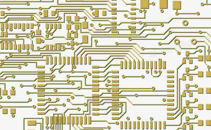
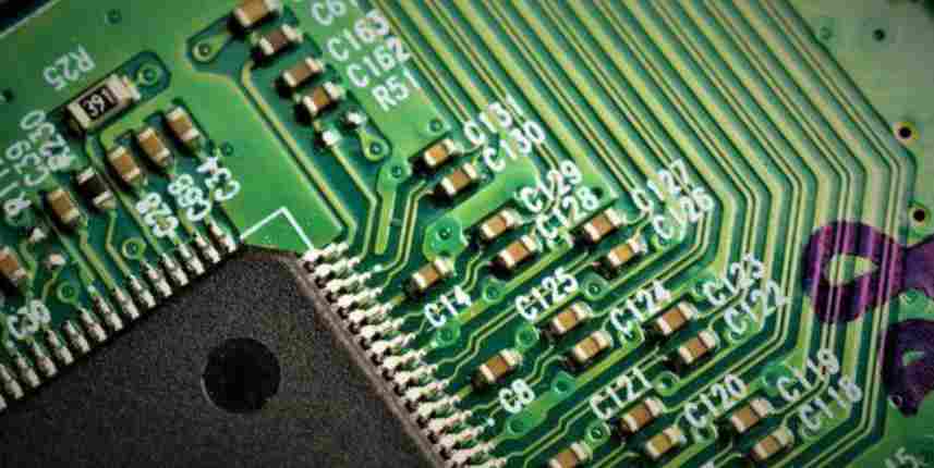
PCB circuit boards play an important role in life today. It is the foundation of electronic components and the highway. In this regard, the quality of the PCB is critical.
To check the quality of a PCB, a number of reliability tests must be performed. The following paragraph is an introduction to testing.
1. Ion contamination test
Objective: To check the number of ions on the surface of the circuit board to determine whether the cleanliness of the circuit board is qualified.
Methods: 75% concentration of propyl alcohol was used to clean the sample surface. Ions can dissolve into propanol, changing its conductivity. The change in conductivity is recorded to determine ion concentration.
Standard: less than or equal to 6.45ug.NaCl/sq.in
2. Chemical resistance test of welding resistance film
Objective: To check the chemical resistance of welding resistance film
Method:
Drops of qs (quantum satisfied) dichloromethane are added to the surface of the sample. After a while, wipe the methylene chloride with white cotton. Check cotton for staining and solder mask for dissolution. Standard: No dye or dissolve.
3. Hardness test of welding resistance layer
Objective: To check the hardness of welding resistance film
Method:
Lay the circuit board on a flat surface. Use a standard test pen to scratch a range of hardness on the boat until there are no scratches. Record the minimum hardness of the pencil. Standard: The minimum hardness should be higher than 6H.
4. Stripping strength test
Purpose: To check the force that can strip the copper wire from the circuit board
Equipment: peeling strength tester
Method:
Strip at least 10mm of copper wire from one side of the substrate. Place the sample plate on the tester. Use vertical forces to strip the remaining copper wire. Power of record. Standard: The force should exceed 1.1N/mm.
5. Weldability test
Objective: To check the weldability of solder pads and through holes on plates.
Equipment: Soldering machine, oven and timer.
Method:
Bake the plate in a 105℃ oven for 1 hour. Dip flux. Flatly put the plate into the solder machine at 235 C and take it out after 3 seconds, check the area of the solder plate for the dipping tin. Place the plate vertically into the soldering machine at 235℃, take it out after 3 seconds, and check whether the through hole is soaked in tin. Standard: Area percentage should be greater than 95. All through holes should be impregnated with tin.
6. Withstand pressure test
Objective: To test the voltage resistance of circuit board.
Equipment: pressure tester
Method:
Clean and dry the sample. Connect the circuit board to the tester. Increase the voltage to 500V DC (direct current) at a speed no higher than 100V/s. Hold it at 500V DC for 30 seconds. Standard: There should be no fault on the circuit.
7. Glass transition temperature test
Objective: To check the glass transition temperature of the plate.
Equipment: DSC (differential scanning calorimeter) tester, oven, dryer, electronic scale.
Method:

Prepare the sample, which should weigh 15-25mg. The samples were baked in a 105℃ oven for 2 hours and then cooled to room temperature in a dryer. Put the sample into the sample table of the DSC tester, and set the heating rate at 20℃/ min. Scan twice and record Tg. Standard: Tg should be higher than 150℃.
8. CTE (coefficient of thermal expansion) test
Objective: To evaluate the CTE of the board.
Equipment: TMA (thermal mechanical analysis) tester, oven, dryer.
Method:
Prepare samples with sizes of 6.35 * 6.35mm. The samples were baked in a 105℃ oven for 2 hours and then cooled to room temperature in a dryer. The samples were put into the sample table of the TMA tester, and the heating rate was set at 10℃/ min, and the final temperature was set at 250℃ to record CTE. 9. Heat resistance test
Objective: To evaluate the heat resistance of plates.
Equipment: TMA (thermal mechanical analysis) tester, oven, dryer.
Method:
Prepare samples with sizes of 6.35 * 6.35mm. The samples were baked in a 105℃ oven for 2 hours and then cooled to room temperature in a dryer. Put the sample into the sample table of the TMA tester and set the temperature rise rate at 10℃/ min. The sample temperature was raised to 260℃.
PCB (printed circuit board) can be divided into rigid PCB and flexible PCB, the former can be divided into three types: single-sided PCB, double-sided PCB and multi-layer PCB. PCBS can be classified into three quality classes based on quality levels: Class 1, Class 2 and Class 3, of which Class 3 has the highest requirements. Differences in PCB quality levels lead to differences in complexity and testing and inspection methods. To date, rigid double-sided PCBS and multilayer PCBS account for relatively large applications in electronic products, and sometimes flexible PCBS are applied in some cases. Therefore, this paper will focus on the quality inspection of rigid double-sided and multilayer PCB. After the PCB is manufactured, it must be checked to see if the quality is compatible with the design requirements. It can be considered that quality inspection is an important guarantee of product quality and the smooth implementation of subsequent procedures.


Just upload Gerber files, BOM files and design files, and the KINGFORD team will provide a complete quotation within 24h.