
Professional PCB manufacturing and assembly
Building 6, Zone 3, Yuekang Road,Bao'an District, Shenzhen, China
+86-13410863085Mon.-Sat.08:00-20:00

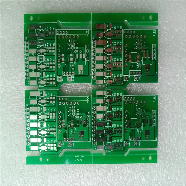
Various acceptable specifications for PCBA welding
With the appearance of new construction methods in circuit board manufacturers, it seems that for a few people who have to perform PTH jack wave soldering on the board surface, lead-free solder paste can be printed into the through-hole first, and then the pins can be squeezed in. As a result, the pins and pins can be firmly soldered at the same time after a fusion soldering. However, this new attempt is still developing gradually.
1、 Lead free solder joint surface is rough
The mainstream of lead-free solder is Sn Ag Cu SAC305 or 405, which is an interpretation of orange peel like appearance. It is difficult for these ternary alloys to reach the ideal state of eutectic eutectic composition in the process of hot melting or cold solidification. The temperature time curve of general fusion welding operation, when the temperature rise and drop in the peak temperature fusion welding section are kept normal, The tin which accounts for the largest amount of SAC solder in the cooling process will take the lead in self cooling and become dendrite (The rest of the stick like protrusion is still in the eutectic part of the liquid, and will be cooled later to become a smooth section. Therefore, there will be many granular protrusions on the overall appearance, and the phenomenon of uniform distribution of pure tin dendrites can be clearly seen in the microsection. In addition, the formation of Ag3Sn white lath like IMC is also obvious to all. In fact, the granular pure tin dendrites in the structure have little negative impact on the strength and reliability It is the microcracking of eutectic zone and IMC of Ag3Sn, which is the origin of cracking during aging.
2、 Allowable specification of lead-free solder joint in case of abnormality
If holes are blown after wave welding of plated through-hole pins, or SMT solder joints show bottoming pinholes, or the surface is sunken, Class1 can accept as long as the solder joints can meet other quality requirements. However, Class2 and Class3 shall be regarded as "process warning". Readers should note that from the principle of quality control and improvement, when a process warning occurs, the customer must see the improvement plan and implementation determination before considering accepting the current product. Therefore, the "process warning" has become a more serious overall problem.
Explanation of insufficient fluidity of liquid lead-free solder:
If the temperature difference between the welding peak temperature needle and the solder melting point is interpreted as "fire power" or fluidity, the average fire power for tin lead fusion welding is 42 ℃, and the average temperature for tin lead wave welding is 67 ℃. However, since the melting point of lead-free solder has increased by 34 ℃ or 44 ℃ compared with tin lead, in order to prevent parts, components and plates from being scalded by strong heat, the firepower of lead-free fusion welding and wave welding has to be reduced to 28 ℃ and 48 ℃. In this way, when the fire power is not strong, the fluidity becomes slow and the viscosity increases, of course, it is easy to have many shortcomings of bridging short circuit.
Moreover, in the lead-free wave soldering tin pool, once the copper contamination exceeds 0.1% by wt, the solder in the pool is m P will rise by another 3 ℃. Under the relatively high peak temperature, the fire power required for lead-free welding is certainly insufficient. This kind of sluggishness of liquid material will inevitably lead to muddling, so all kinds of embarrassing tin bridge and tin mesh, as well as many serious shortcomings that are not clean and neat, are also emerging. If the copper can not be removed, the pure copper can only be added to dilute the copper pollution.
The soldering temperature of lead-free wave soldering has reached 265-270 ℃, causing great damage to various copper parts on the PCB surface. Due to the acceleration of copper melting (dissolution) rate and the increase of copper pollution, the melting point will rise and flow more slowly, not only will the plate surface be covered with broken tin residue, but also the copper content in the solder joint and the pool will generate needle like crystal IMC of Cu6Sn5. When such foreign matters are carried out by the motor, they often make the board face a miserable scene of thorns and needle like crystals, which will lead to more disasters later. It seems that lead-free wave soldering is coming to an end, and it is really impossible to play.
When the solder is no longer composed of eutectic eutectic, the slurry must appear during hot melting and condensation. In fact, the coexistence of solid and liquid phases is quite unstable. Once the automatic conveying is disturbed by external forces such as vibration and shaking, not only the local solder (the pure part of the finger) will rapidly solidify to form bone like dendrites, or there will be stress stripes and other obvious appearances; Its surface is like the appearance of exposed vascular processes of blue tendons, which is specially called "interference welding". The original surface of lead-free solder joints is not smooth enough, but if there are too many stress stripes and too obvious, it is still caused by interference welding, and the third level plates are still considered as defects.
As for the cracking of surface mount solder joints, most of the reasons are due to the impact of excessive stress during the soft slurry period, which leads to the cracking of lead-free solder joints after cooling. Third level plates are considered as disadvantages. Such sloppy defects in current tin lead solders also occasionally occur on the board after wave welding, mainly due to insufficient firepower, slow liquidity, and increased viscosity.
Due to the thermal expansion coefficient (CTE) in the Z direction of PCB thickness, under the strong heat of lead-free wave soldering, the average CTE is 55-60 PPM/℃, while the CTE of lead-free solder itself is only 20-25 PPM/℃, so that when the solder is not firmly soldered, it is pulled apart by the difference of CTE. If lead pollution or bismuth pollution occurs in lead-free solder joints, it will be even worse. Sometimes, even the outer edge of the copper ring is pulled up when the solder joints are firm. For version D, if the main board surface with lead-free wave soldering upward is cracked, the third level boards can be accepted.
In fact, various IPC specifications do not involve the quality of single panel. The main reason is that the PCB and PCBA industries in the United States no longer produce single panel and single panel assembly products for many years. For American brands with demand, they only need to purchase the final complete machine from Asian manufacturers to become their own brand. Therefore, the technical and quality documents required by the single panel process are always lacking.
Since most lead-free solders are difficult to reach eutectic composition, most pure tin will first be solidified into dendrites during the cooling and solidification process of solder joints. In this high temperature, there are many pure interdendritic and high viscosity liquid eutectic alloys. Once the slurry state coexisting with solid and liquid is maintained for too long or interfered by a large amount of external force vibration, the liquid part in the final cooling center will form a strong and rapid cooling shrinkage, and then the so-called necking will occur.
The allowable specification of version D for such lead-free welding cracks with large necking is: tin bottom can still be seen before the welding body crack is too deep; Or such cracks have not touched the base such as pins, welding pads or hole copper wall, they can still be accepted. If there is no tin bottom for the closing or cracking of lead-free solder joints, or the pins or pads have been directly touched, it is still considered as a defect. As for those with lead welding, the welding points are always not allowed to have necking or hot cracking.


Just upload Gerber files, BOM files and design files, and the KINGFORD team will provide a complete quotation within 24h.