
Professional PCB manufacturing and assembly
Building 6, Zone 3, Yuekang Road,Bao'an District, Shenzhen, China
+86-13410863085Mon.-Sat.08:00-20:00

Flexible and Rigid for PCB Design - Guidelines for Flexible PCB Stiffeners
In PCB components, PCB stiffeners are typical necessities in many flexible circuit designs. Flexible circuit board is one of the popular printed circuit boards in the market.
In this article, we will address the following points:
What are the stiffeners in a flexible PCB?
What are the uses of PCB stiffeners?
Why do flexible PCBs need stiffeners?
Flexible PCB stiffener material
How to use flexible PCB stiffeners?
Differences between rigid flexible and hard PCB based on FR4 stiffener
Precautions for stiffeners
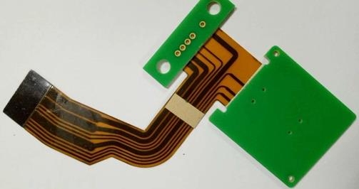
Rigid flexible laminated sample with stiffeners
What are the stiffeners of flexible PCB?
The reinforcement is not an electrical part of PCB, but is responsible for providing mechanical support. It is an additional mechanical part that can provide mechanical support for PCB during assembly.
Flexible PCB also has disadvantages. They may be too flexible! They may not be rigid where stiffness is required. This is where human experience is put into practice. We created PCB stiffeners for these cases.
What is the use of stiffeners?
When we have to harden specific areas in flexible circuits, we use stiffeners. First of all, we need to understand that PCB stiffeners are not part of circuit board design. This will not bend the circuit and will protect the solder joint integrity of the part. The following are some reasons for requiring stiffeners:
A specific area of a circuit board that mechanically supports SMT and/or PTH components.
Maintain the legal thickness in the flex circuit.
Supports PCB assemblies and connectors.
Limit flexible parts to rigid areas as required.
It is convenient to better handle thin circuit boards.
Keep some areas of the flexible circuit flat and stable.
Conform to zero insertion force (ZIF) connector specifications.
The bending radius of the circuit is increased at the intersection of the rigid and flexible parts. This avoids bending the stress on the part during multiple bending operations.
Route and reserve the array. To achieve this, the reinforcing material will extend into the array.
Why do flexible PCBs need stiffeners?
Stiffeners are required in the following cases:
Components are placed in elastic areas.
The weight of the component placed in the bending area will exert pressure on the bending material.
In order to place the SMT gasket assembly, it is necessary to create a flat and solid surface on the flexible part.
Connectors that require multiple insertions will require a reinforcement to help reduce pad stress.
Flexible PCB stiffener material
Choosing the right material for PCB reinforcement is critical because it has extensive advantages in our applications. In this section, we will look at reinforcing materials commonly used in flexible circuits. Generally, PCB reinforcing plate is made of FR4 or rigid polyimide.
FR4 is a glass fiber woven laminate impregnated with epoxy resin. Polyimides are produced from high-temperature polymers that form film layers. You can stack many layers for greater thickness.
In some cases, you may need to use other materials (such as stainless steel or aluminum) as PCB reinforcing plates. However, these materials are more expensive.
Typical stiffener thickness:
Stiffeners are 0.002 inch to 0.059 inch thick. Kapton stiffeners range in thickness from 0.002 inch to 0.010 inch, and rigid stiffeners range in thickness from 0.008 inch to 0.059 inch. The thicker the PCB reinforcement, the more support it will provide. But each design pursues a different thickness. If the circuit board is to be made thicker, polyimide stiffeners must be used.
How to use PCB stiffeners?
When we use stiffeners for plated through hole (PTH) components, the stiffeners should be located on the same side of the flexible wire inserted into the component. This allows access to pads on flexible circuits. You can also connect the stiffeners to both sides of the part, but the PCB assembly will need to check the array configuration. When we need an assembly array for flexible circuit design, it is common and cost-effective to include FR4 stiffeners at the entire array boundary. This is summarized as a rigid array. In most cases, this allows parts to be automatically assembled in the same way as rigid circuit board designs. It also eliminates the need for any other toolboards, etc.
Typically, we will use heat and pressure (thermal bonding) to connect the stiffeners to the circuit. We can also use pressure-sensitive adhesive to paste PCB reinforcement plates.
Two popular adhesives usually belong to pressure sensitive adhesive (PSA) and thermal adhesive. The choice of adhesive depends on various performance requirements, such as heat exposure, chemical resistance and adhesion to various materials.
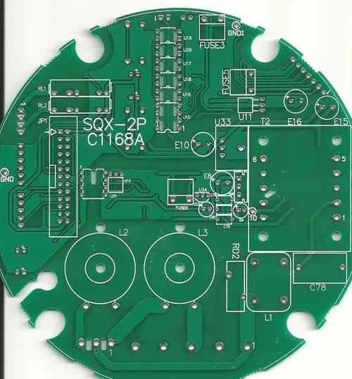
Rigid - The difference between flexible and rigid PCBs
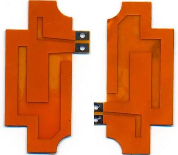
The rigid flexible board is a flexible PCB, but it is combined with the FR4 reinforcement board to enhance the rigidity during assembly. Rigid flexible circuits are referred to as hybrid flexible circuits including rigid and flexible substrates. We laminated them into a single structure.
Even on the gasket, there is no trace on the rigid and flexible part. This rigid part only enhances the rigidity at this position. In other words, it only provides mechanical support for flexibility. However, for rigid flexible PCB, both rigid body and flexible components are designed with wiring, and we connect them through holes. In other words, it is not a mechanical support, but an electrical connection of rigid flexible PCB.
Rigid flexible PCB has electrical connection, while rigid PCB is used for mechanical support.
Precautions for PCB reinforcement
Stiffeners shall overlap the exposed overlay by 0.030 inch to reduce stress. Coverlay is used as a solder barrier for flexible PCBs.
When using multiple stiffeners, maintain the same stiffener thickness.
To learn more about flexible design considerations, see Avoiding common flexible PCB errors and successful design
When we need rigid areas in flexible circuits, stiffeners can be used to protect the components or connectors connected to them. This protects the circuit from bending and protects the integrity of solder joints. FR4 material is usually used for stiffeners, which can be connected with thermosetting acrylic adhesive or pressure-sensitive adhesive. This meets our requirements for fixing specific areas in flexible circuits. PCB assembly and PCB processing manufacturers explain flexible and rigid flexible PCB stiffener guidelines for PCB design.


Just upload Gerber files, BOM files and design files, and the KINGFORD team will provide a complete quotation within 24h.