
Professional PCB manufacturing and assembly
Building 6, Zone 3, Yuekang Road,Bao'an District, Shenzhen, China
+86-13410863085Mon.-Sat.08:00-20:00


To make a good pcb board design, not only simple design is good, in the design of these are need to pay attention to.
1. If the designed circuit system includes FPGA devices, Quartus II software must be used to verify pin allocation before schematic drawing. Some special pins in FPGA cannot be used as normal IO.
2, 4 layers from top to bottom: signal plane layer, ground, power supply, signal plane layer; The six layers from top to bottom are: signal plane layer, ground, signal internal electrical layer, signal internal electrical layer, power supply, signal plane layer. For boards with more than 6 layers (advantages are: anti-interference radiation), the internal electrical layer is preferred to be routed. If not, the plane layer is selected, and the ground or power layer is prohibited to be routed (cause: the power layer will be divided, resulting in parasitic effect).
3, multi-power system wiring: such as FPGA+DSP system to do 6 layers of board, generally at least 3.3V+1.2V+1.8V+5V.
3.3V is generally the main power supply, directly lay the power layer, through the hole is easy to distribute the global power network;
5V May be a power input, and only copper is needed in a small area. And as thick as possible.
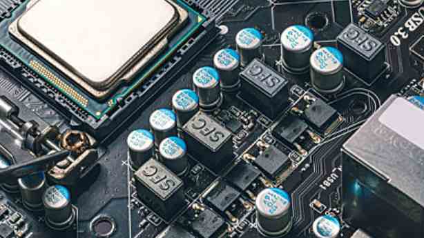
1.png
1.2V and 1.8V are the core power supply (if directly connected by wire, it will encounter great difficulties in the face of BGA devices). In the layout, 1.2V and 1.8V should be separated as far as possible, and the components connected within 1.2V or 1.8V should be arranged in a compact area and connected by copper skin, as shown in the figure:
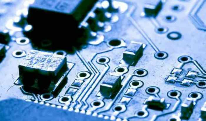
2.png
In short, because the power network is spread over the entire PCB, it would be complicated to use the wiring method and it would take a long way around, so using the copper coating method is a good choice!
4. The crossing mode is adopted between adjacent layers: it can not only reduce the electromagnetic interference between parallel wires, but also facilitate the wiring.
5, analog digital to isolation, how isolation method? The layout will be used for analog signal devices and digital signal devices separate, and then cut from the middle of the AD chip!
The analog signal is laid on the analog ground, and the analog ground/analog power supply and the digital power supply are connected through a single point of inductance/magnetic beads.
3.png
6. PCB design based on PCB design software can also be regarded as a software development process. Software engineering pays most attention to the idea of "iterative development" to reduce the probability of PCB errors.

(1) schematic check, especially pay attention to the power supply and ground of the device (power supply and ground are the blood of the system, can not be the slightest neglect);
(2) PCB packaging and drawing (confirm whether the pins in the schematic diagram are wrong);
(3) After confirming the PCB packaging size one by one, add verification labels to the packaging library of this design;
(4) Import the netlist, and adjust the sequence of signals in the schematic diagram while laying out (OrCAD component automatic numbering function cannot be used after laying out);
(5) manual wiring (side cloth side check the power network, as previously said: the power network uses copper paving, so less wire);
In a word, the guiding idea of PCB design is to draw the package layout and wiring while feedback correction schematic diagram (from the accuracy of signal connection, the convenience of signal routing).
7. Crystal oscillator is as close to the chip as possible, and the crystal oscillator is not as far as possible, and the ground network copper sheet is paved. Multiple clocks are wired in tree clock tree mode.
8. The signal layout on the connector has a great influence on the difficulty of wiring, so it is necessary to adjust the signal on the schematic diagram while wiring (but do not re-number the components).
9. Design of multi-plate connector:
(1) Use bar connection: the upper and lower interfaces are consistent;
(2) Straight socket: The upper and lower interfaces are mirrored symmetrically, as shown below:
10. Design of module connection signal:
(1) If the two modules are placed on the same side of the PCB, the sequence number is large and small and large (mirror connection signal);
(2) If the two modules are placed on different sides of the PCB, the sequence number should be changed from small to large.
Doing so allows the signals to cross over as shown on the right above. Of course, the above method is not a rule. I always say that everything changes as it needs to (and this is something you can only learn), but there are many situations in which designing this way works.
11. Design of power supply ground loop:
The ground circuit of the power supply above is large and susceptible to electromagnetic interference.
In the figure above, the circuit area is reduced and the electromagnetic interference is reduced (679/12.8, about 54 times) by improving the proximity of the power supply to the ground wire. Therefore, power and ground should be close to the line as far as possible! The signal lines should be avoided and walked as far as possible to reduce the mutual inductance effect between signals.


Just upload Gerber files, BOM files and design files, and the KINGFORD team will provide a complete quotation within 24h.