
Professional PCB manufacturing and assembly
Building 6, Zone 3, Yuekang Road,Bao'an District, Shenzhen, China
+86-13410863085Mon.-Sat.08:00-20:00

Precautions for welding chip capacitors with surface roughness
MLCC (Chip Multilayer Ceramic Capacitor) has become one of the most commonly used electronic circuits in SMT. On the surface, a million cubic centimeters looks simple, but in many cases, design engineers or production technicians do not have enough knowledge of a million cubic centimeters Some surface roughness companies also have some misunderstandings in the application of millions of cubic centimeters, believing that millions of cubic centimeters is a very simple component, so the process requirements are not high In fact, one million cubic centimeters is a very fragile component, so you must pay attention to it in application- Let's talk about some problems and precautions in the application of millions of cubic centimeters
Chip multilayer ceramic capacitors (million cubic centimeters) have become one of the most commonly used components in electronic circuits. On the surface, a million cubic centimeters looks very simple, but in many cases, design engineers or production and process personnel have insufficient knowledge of a million cubic centimeters. Some companies also have some misconceptions in the application of millions of cubic centimeters, believing that millions of cubic centimeters are a very simple component, and this process is not demanding. In fact, millions of cubic centimeters is a very fragile component, so we must pay attention to it when applying it - let's talk about some problems and precautions in the application of millions of cubic centimeters.
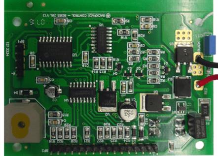
Circuit board

With the continuous development of science and technology, millions of cubic centimeters of chip capacitors can now be realized in hundreds or even thousands of layers, each with a thickness of micrometers. In this case, slight deformation is easy to cause cracks. In addition, under the same data, size and withstand voltage, the higher the capacity, the more layers, and the thinner each layer, the easier it is to break. On the other hand, when the data, capacity and withstand voltage are the same, small capacitors require that each layer of dielectric be thinner, which makes it easier to disconnect. The hazard of crack is electric leakage, which may lead to safety problems such as internal interlayer dislocation and short circuit when it is serious. In addition, a very troublesome problem with cracks is that they are sometimes hidden and may not be found during factory inspection of electronic equipment. They were officially exposed to customers. In this case, it is of great significance to prevent the cracks in the chip capacitor in one million cubic centimeters.
When one million cubic centimeters of chip capacitor is impacted by temperature, it is easy to crack from the welding end. At this point, small size capacitors are relatively better than large size capacitors. The principle is that large capacitors will not transmit heat to the whole capacitor so quickly. Considering that the temperature difference between different points of the capacitor body is large and the expansion size is different, stress will be generated. The reason is the same as that when pouring boiling water, thick glasses are easier to break than thin glasses. In addition, during the cooling process of the chip capacitor with a million cubic centimeters after welding, the expansion coefficient of the chip capacitor with a million cubic centimeters is different from that of the printed circuit board, which will generate stress and thus lead to cracks. To avoid this problem, a good welding temperature profile is required during reflow welding. If wave soldering is used instead of reflow soldering, such failures will be greatly increased. It is necessary to avoid manual welding with soldering iron for MLCC. However, things are always not so ideal. Welding by hand with a soldering iron is sometimes unavoidable. For example, for electronic manufacturers dealing with printed circuit boards, some products are very small. When outsourcing manufacturers are unwilling to accept this order, they can only weld manually; Manual welding is usually adopted when producing samples; Under special circumstances, manual welding must be carried out during rework or rework or repair; When repairing the capacitor, the repairman is also doing manual welding. When manual welding is unavoidable for millions of cubic centimeters, it is necessary to attach great importance to the welding process.
First, the process and production personnel must be informed of the thermal failure of the capacitor, so that they can attach great importance to this problem in their minds. Secondly, it must be welded by professional and technical workers. There are also strict requirements for welding process. For example, a thermostatic soldering iron must be used. The soldering iron should not exceed 315 ℃ (to prevent production workers from raising the welding temperature), and the welding time should not exceed 3 seconds. Select the appropriate flux and paste. First, clean the pad so that a million cubic centimeters will not be subjected to great external force. Pay attention to the welding quality. The best manual welding is to put tin on the bonding pad first, then melt the tin on the bonding pad with a soldering iron, and then put the capacitor on it. During the whole process, the soldering iron only contacts the bonding pad, not the capacitor (it can be moved close). Use a similar method (heating the tinned pad on the pad instead of directly heating the capacitor) to solder the other end.
Mechanical stress can also easily lead to cracking of millions of cubic centimeters Since the capacitor is rectangular (parallel to the surface of PCB), and the short side is the welding end, it is natural that the long side is prone to problems when stressed Therefore, the direction of the force must be considered when arranging the circuit board For example, the relationship between the deformation direction and the capacitor direction when the circuit board is divided In the production process, try not to discharge the capacitor at the place where the printed circuit board may have large deformation For example, PCB positioning and riveting, mechanical contact of test points during veneer testing, etc It will cause deformation In addition, semi-finished PCB boards cannot be stacked directly, etc

Strength and use of SMT mounter
Dec 02,2022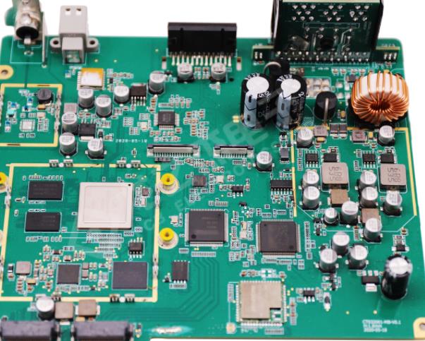


Just upload Gerber files, BOM files and design files, and the KINGFORD team will provide a complete quotation within 24h.