
Professional PCB manufacturing and assembly
Building 6, Zone 3, Yuekang Road,Bao'an District, Shenzhen, China
+86-13410863085Mon.-Sat.08:00-20:00


Knowledge of electronic circuits essential for PCBA electronics engineers
As a specialized hardware design engineer, you must first have excellent basic skills. You must have an overall understanding of circuit schematics with technical parameters, be able to divide functional modules, find signal flows, and determine the role of components.
A circuit diagram is a type of circuit diagram drawn by a person with recognized symbols for use in research and engineering needs. You can understand the actual situation of the circuit through the circuit diagram. That way, when we analyze a circuit, we don't have to flip the real thing over and over again, just keep a drawing. When designing a circuit, it can also be done on paper or on a computer. After confirming that it is perfect, you can install it. With debugging and improvement, you can succeed. We can even use advanced computer software to assist in circuit design and even conduct virtual circuit experiments, which greatly improves work efficiency.
Master several common circuit analysis methods and be familiar with the types of circuits and the appropriate analysis steps for each method.
1. Ac equivalent circuit analysis method. First draw an AC equivalent circuit, and then analyze the AC state of the circuit, that is, when the circuit has a signal input, if the voltage and current of each link in the circuit change according to the signal law input, is it amplified? , Oscillating or cutting, plastic surgery
2. Analysis method of DC equivalent circuit. Draw the DC equivalent circuit diagram, analyze the DC system parameters of the circuit, understand the static operating point and bias characteristics of the transistor and the interstage coupling mode. The states and functions of the related components in the circuit are discussed. For example: the operating state of the transistor, such as saturation, magnification, cutoff area, diode conduction or cutoff, etc.
3. Frequency characteristic analysis method. It mainly depends on whether the frequency of the circuit itself is compatible with the spectrum of the signal it is processing. Roughly estimate your center frequency, upper and lower limit frequencies, and frequency bandwidth, such as: various circuits, such as filtering, notch, resonance, frequency selection, etc.
4. Constant time analysis method. It mainly analyzes the characteristics of circuits, R, L, C and diodes. The time constant is a parameter that reflects the accumulation rate and energy consumption in the energy storage element.
Classification of electronic circuit diagrams: Often encountered electronic circuit diagrams are schematic diagrams, block diagrams, assembly drawings and printed versions.
A schematic diagram is a circuit diagram used to reflect the working principle of an electronic circuit, also known as an "electrical schematic diagram". This type of diagram is often used in circuit design and analysis because it directly reflects the structure and working principle of an electronic circuit. By analyzing the circuit, the actual operation of the circuit can be understood by identifying the symbols of various circuit components drawn in the diagram and the connection methods between them. The diagram below shows the radio circuit diagram.
A block diagram is a circuit diagram that shows the working principle and composition of a circuit with boxes and cables. Basically, this is schematic. However, in this type of graphics, there are few symbols other than boxes and lines. The main difference between this schematic and the one above is that all circuit components and their connection methods are drawn in detail in the schematic, while the block diagram only divides the circuit installation function into sections and represents each section as an A-box, simple text instructions in the boxes, and connections between the boxes (sometimes lines with arrows) to explain the relationships between the boxes.
The block diagram can only be used to reflect the general working principle of the circuit, and in addition to showing the working principle of the circuit in detail, it can also be used as the basis for collecting components and making circuits. The diagram below shows a block diagram of the radio circuit above.
It is a graph used for circuit assembly, and the symbols on the graph are usually the physical Outlines of the circuit components. We only need to connect some components of the circuit in the same way as shown in the figure to complete the assembly of the circuit. The circuit diagram is usually suitable for beginners.
Assembly drawings vary according to different assembly templates. Most of the time, because electronic products use the printed circuit board described below, the printed circuit board diagram is the main form of assembly diagram.") https://www.kingfordpcb.com/yuan.php
https://www.kingfordpcb.com/yuan.php
The full name of a printed circuit board diagram is "printed circuit board diagram" or "printed circuit board diagram". It is actually the same type of circuit diagram as the assembly diagram, which is used to assemble the actual circuit.
The printed circuit board covers the insulating board with a layer of metal foil, and then etches away unnecessary foil in the circuit. The remaining foil is used as the connecting wire between the circuit components, and then the elements in the circuit are assembled. The device is mounted on the insulating board, and the remaining metal foil on the board serves as a conductive connection between the components to complete the circuit connection. Because the metal on one or both sides of this circuit board is copper, the printed circuit board is also called a "copper-clad plate." The layout of components on a printed circuit board is often very different from the schematic.
This is mainly because in the design of the printed circuit board, the layout and connection of all components are mainly considered, and many factors must be considered, such as component volume, heat dissipation, anti-interference and anti-coupling. A printed circuit board designed in combination with these factors is difficult to fully conform to the schematic from the outside. In fact, it can better realize the function of the circuit.
With the development of science and technology, printed circuit board production technology has been greatly developed. In addition to single-board and double-board, there are a variety of boards, widely used in daily life, industrial production, defense construction, aerospace and many other industries.
Of the four forms of circuit diagrams introduced above, the electrical schematic is the most commonly used and the most important. If you can understand the schematic, you can basically understand the circuit principle, draw block diagrams, design assembly drawings and printed circuit board drawings. It's simple. After mastering the schematic diagram, the maintenance and design of household appliances are also very convenient. Therefore, the key is to master the program.
The composition of the circuit diagram: The circuit diagram is mainly composed of four parts: component symbols, connections, nodes and comments.
The component symbol represents a component in an actual circuit whose shape is not necessarily similar to, or even completely different from, the actual component. However, it usually shows the characteristics of the component, and the number of pins is consistent with the actual component.
The wiring represents the wires in the actual circuit. Although in the schematic it is a wire, it is usually not a wire, but a common copper foil of various shapes on a printed circuit board, like many copper foils in radio equipment. The wiring on the printed circuit board is not necessarily straight, but it can also be a copper film of a certain shape.
Nodes represent connection relationships between various component pins or various cables. All component pins and cables connected to the node conduct electricity regardless of the number.
Comments are very important in a circuit diagram, and all text in a circuit diagram can be classified as comments: classes. If you look closely at the diagram above, you will see that there are comments at various places on the circuit diagram. They are used to describe models, names, etc. Of components.
If you do not know the function of the circuit, you can first analyze the relationship between the input and output signals of the circuit. Like the law of signal change and the relationship between them, the phase problem is in-phase or out-of-phase. The circuit and its constituent forms are an amplifier circuit, an oscillator circuit, a pulse circuit or a demodulation circuit.
Electrical equipment maintenance and circuit designers need to analyze circuit schematics to understand the functions and working principles of electrical equipment in order to carry out the work at hand. You will divide the functional blocks and can group the components of the entire circuit according to different functions so that each functional block forms a combination of specific functional components, such as a basic amplifier circuit, a switching circuit, and a switching circuit. Convert.
By analyzing the circuit, the actual operation of the circuit can be understood by identifying the symbols of various circuit components drawn in the diagram and the connection methods between them. A schematic diagram is a circuit that reflects the working principle of an electronic circuit.
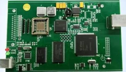
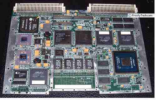
A PCB diagram is a map of the circuit board, which details the wiring of the board and the location of the components.
View the circuit diagram First look at the power supply section to understand the power supply from which the circuit operates, AC or DC, single or multiple power supplies, and voltage levels. After clearing the branch circuit, the difference is whether it is a digital circuit or an analog circuit. Analog circuits focus on signal acquisition. Signal source found. There are RF, audio, all kinds of sensors, instruments and other circuits. The analysis signal is AC, DC or pulse is voltage type or current type. Analyze the function of subsequent circuits to find out whether it is demodulation, amplification, shaping, or compensation. Finally, look at the output circuit, whether it is modulating or conducting. Digital circuit analysis logic function and circuit function.
First of all, to understand the circuit board, it is best to understand its electrical schematic diagram (that is, circuit diagram), understand the annotation method of electronic components and its working principle, and understand its normal parameters and parameters. Some common components. If you understand the role of normal circuits, etc., and then analyze the circuit board (called a printed circuit board), you can quickly understand how it works and some of the things you need to know.
Molecular circuit module, then find the central component of the subcircuit (of course, you must be familiar with this component) to find the electrical connection between the subcircuit modules, and finally find the output and input or function of the entire circuit.
The entire circuit of the machine has certain functions and is composed of unit circuits. The unit circuits form signal processing branches with certain functions, and then these branch circuits form the complete circuit of the machine. The first thing you need to understand about the circuit diagram is the type of circuit, which can be audio, video, digital or hybrid. Then, the circuit knowledge of the corresponding unit is used to interpret these circuits and simultaneously analyze the AC signal level to the DC level. The DC part of the circuit is the basis of normal circuit operation. The AC signal can only be processed after the DC circuit is normal. Without good DC conditions, the circuit will not work properly.
You also need to analyze from the amplifier's frequency level and gain level. When the circuit processes signals of different frequencies, because of the nonlinear components in the circuit, there will be different processing results for different frequencies. With different amplification functions, the circuit will be designed to intentionally process the required frequency signal to meet the needs of the machine function. Then, there is the relationship between the unit circuits and the relationship between the input and output of the unit circuits.
How does the AC signal change after passing through these circuits? After understanding how each branch works, you can analyze how the entire machine works. Sometimes there is a signal connection between the branch circuits. For example, the reverse line pulse of a television output circuit is used for color. The decoding circuit, the output circuit and the color decoding circuit are interconnected with each other. At this point, these branches can be understood as another unit circuit, which is then analyzed.
I think there is a sequencing problem here: for high frequency circuits, first of all, you have to understand the function of the circuit and the input and output relationships. With a general understanding, it is like holding a bull by the nose, because although the circuits are different and the devices are different, their input and output ratio spectrum does not change. Then we discuss the basic principle and method to realize this functional transformation, especially the partial analysis.
When designing a circuit, you should first look at the circuit schematic, but first you need to understand the pins and basic functions of the desired chip. This will help you better understand how the circuit works so that you can apply it to your own circuits and make it easier to cut and expand the circuit.
First of all, have an overall understanding of the circuit schematic, and divide various functional modules, such as power module, controller module, storage module, audio module, GPRS module and so on. Go through each module one by one and finally look at them together to get a general idea of what the circuit will do. It is best to be familiar with the principles of common or common unit circuits (such as power modules, voltage regulator modules, memory modules, etc.) and common chips (such as 7805, 7812, etc.).
Divide the circuit you want to design into several modules for design and eventual integration on different schematics. When there is a signal input in the circuit, it is necessary to make a rough estimate of the voltage and current at each basic point. For a circuit with amplifiers R, L and C, it depends on whether it is an oscillating circuit, an amplifying circuit or a shaping circuit. After self-analysis and your own design, you will have a better understanding and understanding of the basic principles of the circuit, and accumulate design and debugging experience in the future design.


Just upload Gerber files, BOM files and design files, and the KINGFORD team will provide a complete quotation within 24h.