
Professional PCB manufacturing and assembly
Building 6, Zone 3, Yuekang Road,Bao'an District, Shenzhen, China
+86-13410863085Mon.-Sat.08:00-20:00

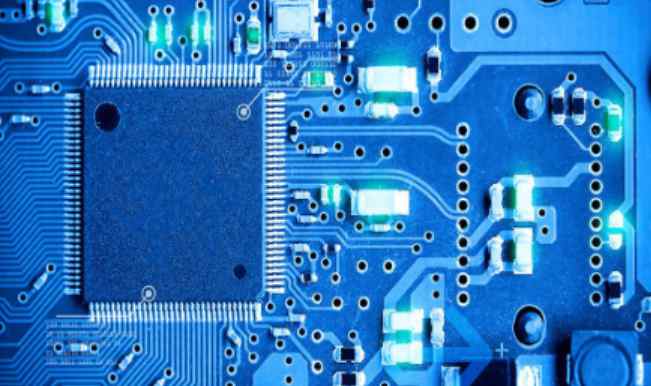
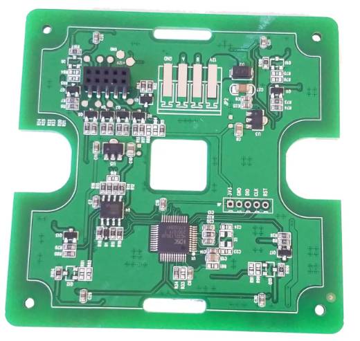
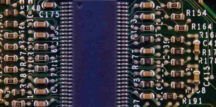
pcb circuit boards will do characteristic impedance when they are applied. The so-called characteristic impedance of pcb circuit boards is mainly the parameters of resistor and reactance, which plays a blocking effect on AC current. To carry out characteristic impedance work during manufacturing, the key elements are:
1, PCB circuit (bottom of the board) to fully consider the plug assembly of electronic components, plug fully consider the conductivity and signal transmission performance and other issues, so it will be stipulated that the lower the characteristic impedance, the better, resistance is less than 1&TImes per square centimeter; Below 10-6.
2, PCB circuit board in the production and manufacturing process to go through the copper, electroplating tin (or electroless plating, or hot spray tin), solder joints and other production process stages, and the raw materials used in these stages must ensure that the resistance bottom, to ensure that the overall characteristics of the circuit board impedance is low to achieve product quality regulations, can no problem operation.
3. The electroplated tin of PCB circuit board is the most prone to problems in the production of the whole circuit board, and it is an important link of the harm characteristic impedance. Chemical plating tin layer is the biggest flaw is easy to fade (both easy oxidation or delixing), poor brazing, will cause the circuit board difficult welding welding, characteristic impedance is too high resulting in poor conductivity or instability of the whole board performance.
4, PCB circuit board in the conductor will have a variety of signals transmission, when to improve its transmission speed and must improve its frequency, if the line itself because of etching, laminated thickness, wire width and other elements are not the same, may lead to the characteristic impedance value change, so that the signal distortion, resulting in circuit board performance decline, so it is necessary to control the characteristic impedance value in a certain range.

Dowel pins are not suitable for multi-connector applications
Some connector manufacturers offer optional dotting pins, which are usually located on opposite sides of the bottom of the connector. These dotting pins facilitate manual placement, can be used to help Orient connectors on the PCB board, and for single-connector applications, they do not add to overall tolerance accumulation.
While dotting pins are useful for both manual placement and orientation, they are not recommended for multi-connector applications because of their impact on overall tolerance accumulation.
However, for multi-connector applications, we do not recommend using dotting pins because of their impact on the overall tolerance accumulation. If orientation on the PCB board is still required, a better option is to drill some oversized holes in the PCB board and then use a machine to place the connector.
Again, it is not recommended to use clamps or pins to assist in connector placement. These methods often rely on drilling a hole on the PCB relative to the original drawing, but the hole's position tolerance is often poor relative to the other connector, which reduces the overall accuracy of the final placed connector.
For multi-connector applications, A better approach is to position all pads starting at position A1 in solderpad array A, and then position the connectors precisely on the pads before reflow.
Use fastening screws to secure the PCB board
Some particularly strong applications may require the use of fastening screws to protect both PCB boards. In this case, the screw should be as close to the connector system as possible (Figure 5).
Placing them close together will concentrate stress near the connectors and reduce the span of the PCB board that is not supported. Increased span can cause bending stresses in PCB boards, which may adversely affect other components, especially surface mounted components.
To avoid over-specification loading, designers should always verify the connector insertion force and pull-out force, which can be found in the product quality test report.
Although the miniaturization trend makes it more challenging, it is possible to use multiple connector groups on two PCB boards by using best design practices. These include conducting a system tolerance study to determine connector alignment deviations, then following the connector provider's recommended placeholder dimensions and die design, and using the machine to place the components.
In addition, it is recommended to work closely with the connector provider early in the design process, as they can advise on the type and placement of the connectors, as well as advice on how to minimize the overall stress on the PCB and connectors to help ensure design success.


Just upload Gerber files, BOM files and design files, and the KINGFORD team will provide a complete quotation within 24h.