
Professional PCB manufacturing and assembly
Building 6, Zone 3, Yuekang Road,Bao'an District, Shenzhen, China
+86-13410863085Mon.-Sat.08:00-20:00

Surface Roughness Mounter Components and Throwing Data
With the extensive application of SMT (Surface Mount Technology) in electronic products, the SMT (Surface Mount Technology), the key equipment for surface roughness production in, has also been developed rapidly. However, some errors will inevitably occur when using SMT How to eliminate these faults and ensure that the machine is in the best working condition is an important task in the daily use and management of the placement machine The following describes some common faults and troubleshooting methods of the mounter in daily use
Component picking error
The components are removed from the package and adhesive tape by the high-speed moving placement head and placed on the circuit board. There will be some bad absorption failures, such as not being picked up and missing after picking up. These failures will result in a large number of component losses. Poor part picking is usually caused by the following reasons:
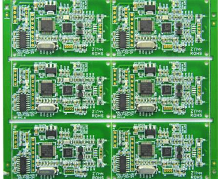
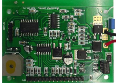
Circuit board

(1) Insufficient vacuum negative pressure. When the components are sucked in, the vacuum negative pressure should be higher than 53.33 kPa, so that there is enough vacuum to suck in the components If the vacuum negative pressure is insufficient, it will not provide enough suction to absorb the components In use, check the vacuum pressure frequently and clean the suction nozzle regularly At the same time, pay attention to the placement head of the polluted surface roughness of the vacuum filter element for each screening procedure Its function is to filter the air source reaching the suction nozzle, replace the polluted black, and ensure smooth airflow
(2) The nozzle is worn, deformed, blocked or damaged, resulting in insufficient air pressure and failure to absorb parts. In this case, the suction nozzle shall be regularly checked for wear, and the nozzle shall be replaced in case of severe wear.
(3) Due to the influence of the feeder, the feeder feeding is poor (feeder gear is damaged), the belt hole on the feeder gear is not stuck, there are foreign matters under the feeder, and the elastic retainer ring is worn), resulting in the component suction deviation, standing or failure to absorb the component, which should be checked regularly, and problems found should be handled in a timely manner
(4) Effect of suction height. The ideal suction height is when the suction nozzle contacts the surface of the component and then presses it down 0.05 mm. If the pressure depth is too large, the component will be pressed into the groove and cannot be taken out. If the suction of the cloth component is poor, the suction height can be adjusted slightly upwards
(5) Due to the problem of incoming materials, some manufacturers have quality problems in the packaging of chip modules, such as large hole spacing error, excessive adhesion between paper tape and plastic film, and too small slot size. Possible reasons not selected
throw
Throw refers to the loss of the component in the placement position. The main reasons are as follows:
(1) The component thickness is set incorrectly. If the component is thin, but the database is set to be thick, when the component does not reach the pad position during placement, the nozzle will be put down and the xy coordinate system work of the PCB will be fixed. The platform moves at high speed again, and the inertia causes flying parts. In this case, the component thickness must be set correctly.
(2) The thickness of the printed circuit board is set incorrectly. If the actual thickness of the printed circuit board is thin, but the database is thick, the support pin will not be able to fully lift the PCB during the production process and the assembly may be put down before reaching the pad position, resulting in data throwing.
(3) Reasons for PCB
1) PCB warpage exceeds the allowable error of the device,
2) Support pin placement. When installing the printed circuit board on both sides, when installing the second side, the support pin is placed on the bottom component of the printed circuit board, which causes the printed circuit board to warp upward, or the support pin is placed unevenly, and some parts of the printed circuit board have no top, which causes the printed circuit board to be jacked up and incomplete.
The above is the explanation given by the editor of pcb circuit board company.
If you want to know more about PCBA, you can go to our company's home page to learn about it.
In addition, our company also sells various circuit boards,
High frequency circuit board and SMT chip are waiting for your presence again.
SMT Grape Ball and Patch Machine Workflow
Dec 02,2022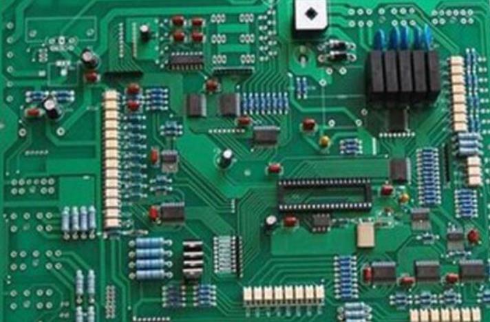


Just upload Gerber files, BOM files and design files, and the KINGFORD team will provide a complete quotation within 24h.