
Professional PCB manufacturing and assembly
Building 6, Zone 3, Yuekang Road,Bao'an District, Shenzhen, China
+86-13410863085Mon.-Sat.08:00-20:00

1) Interference source refers to PCB components, devices or signals that generate interference. Digital language description refers to places with large du/dt and di/dt. Interference can be divided into external interference and internal interference according to its source: external interference refers to the interference that has nothing to do with the structure of the instrument and is determined by the use conditions and external environmental factors, such as lightning, AC power supply, motor, etc; Internal interference is determined by instrument structure layout and production process, such as interference caused by potential difference selected by multi-point grounding, interference caused by parasitic oscillation, interference caused by spike or ringing noise, etc.
2) Sensitive devices refer to the objects easy to be interfered, such as microcontroller, memory, A/D conversion, weak signal processing circuit, etc.
3) The propagation path is the medium for the propagation of interference from the interference source to the sensitive device. The typical interference propagation path is through the conduction of wires, electromagnetic induction, electrostatic induction and space radiation.
The basic task of anti-interference circuit board design is that the system or device will not malfunction or lose its function due to the influence of external electromagnetic interference, nor will it send excessive noise interference to the outside world, so as not to affect the normal operation of other systems or devices. Its design generally follows the following three principles: restrain the noise source and directly eliminate the cause of interference; Cut off the transmission path of electromagnetic interference, or improve the attenuation effect of the transmission path on electromagnetic interference, so as to eliminate the noise coupling between the noise source and the disturbed device; Strengthen the ability of each disturbed device to resist electromagnetic interference and reduce noise sensitivity. At present, the anti-interference technologies used in the system mainly include hardware anti-interference PCB technology and software anti-interference technology.
1) The circuit board design of hardware anti-interference technology. The carrier signal of the inverter circuit of the flywheel energy storage system as high as 20kHz determines that it will generate noise. In this way, the noise and harmonic problems generated by the power electronic devices in the system will become the main interference. They will have an impact on the equipment and nearby instruments. The extent of the impact is related to the anti-interference ability, wiring environment, installation distance, grounding method and other factors of the control system and devices.
The PWM signal generated by the converter controls the output voltage waveform by high-speed on-off DC voltage. The sharply rising or falling output voltage wave contains many high-frequency components, which are the source of noise. Although both noise and harmonic have adverse effects on the operation of electronic equipment, there are differences between them: harmonic usually refers to high-frequency components below 50 times, with a frequency of 2~3kHz; The noise is a high-frequency component of 10kHz or higher. Noise is generally divided into two categories: one is the power electronic device that intrudes into the flywheel battery from outside to make it malfunction; the other is the noise generated by the device itself due to high-frequency carrier, which has adverse effects on the surrounding electronic and telecommunications devices.
The general method to reduce the noise impact is to improve the PCB wiring mode of power line and signal line. The signal line used for control signal must be shielded wire, and the shield wire sheath must be grounded. In order to prevent external noise intrusion, the following measures can be taken: keep the power electronic device away from the noise source, adopt digital filtering for the signal line and ground the shield line.
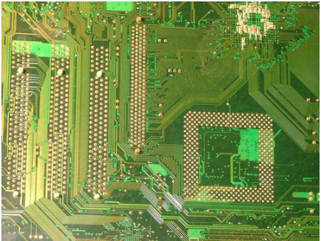
PCB design
The attenuation techniques of circuit board design noise are as follows:
① The attenuation method of wire noise: connect the radio noise filter at the AC input end; A line noise filter is connected at the input end of the power supply and the output end of the inverter, which can be composed of an iron core coil; The radio noise filter and the line noise filter are used together; Connect LC filter at the power supply side.
② The noise radiation attenuation of the wiring from the inverter to the motor can be cut off through the grounding of metal conduits and metal boxes.
③ Generally, the noise radiation of flywheel power electronic device is very small, but if the surrounding instruments are sensitive to noise, the device should be put into a metal box for shielding.
For the suppression of analog circuit interference, because there are analog quantities such as current and voltage to be measured in the circuit, its output signals are weak analog signals, which are very vulnerable to interference. When there is a strong magnetic field near the transmission line, the signal line will have a large AC noise. AC noise can be effectively suppressed by paralleling a capacitor between the input and output of the amplifier and connecting an active low-pass filter at the input. In addition, during A/D conversion, the digital ground wire is separated from the analog circuit ground wire, and a clamping diode is added at the input to prevent abnormal overvoltage signals.
The common interferences of digital circuits include power supply noise, ground wire noise, crosstalk, reflection and electrostatic discharge noise. In order to suppress noise, attention should be paid to the isolation of input and output lines, line selection, wiring, device layout, etc. The processing of input signals is an important part of anti-interference. A large number of interferences are intruded from this point. Generally, measures can be taken from the following aspects:
① Suppression of contact jitter interference; The redundant connecting lines shall be as short as possible, and the mutually twisted shielded wires shall be used as the input lines to reduce the stray capacitance and inductance generated by the connecting lines; Avoid approaching signal line and power line, data line and pulse line.
② Photoelectric isolation technology is adopted, and RC circuit filter is added to the isolation device.
③ Carefully and properly handle the grounding problems, such as the analog circuit ground and digital circuit ground should be separated, the analog circuit and digital circuit on the printed board should be separated, the high current ground should be led to the grounding point separately, and the grid formed by the printed board ground wire should be wide enough.
2) Software anti-interference technology. In addition to taking a series of anti-interference measures in hardware, digital filtering, setting software traps, and using watchdog program redundancy design should also be taken in software to make the system run stably and reliably. In particular, when the energy storage flywheel is in a certain working state for a long time, it is also a method to enhance the reliability by constantly detecting the state in the main cycle and repeating the corresponding operations.
(2) Due to the high working frequency of DSP controller, even if the circuit schematic is designed correctly, if the printed circuit board is not designed properly, the reliability of DSP controller will be adversely affected. For example, if two thin parallel lines of the printed board are close together, the delay of the signal waveform will be formed and the reflected noise will be formed at the end of the transmission line. Therefore, when designing the PCB of DSP controller, we should pay attention to the correct method.
1) Ground wire design. In DSP circuit, grounding is an important method to control interference. If grounding and shielding can be used correctly, most interference problems can be solved. On a circuit board, the DSP controller integrates digital circuit and analog circuit at the same time. When designing the circuit board, they should be separated as far as possible, and the ground wires of the two should not be mixed and connected to the ground wire of the power supply terminal respectively. The grounding wire shall be thickened as much as possible and form a closed loop at the same time.
2) Configure decoupling capacitor. In DC power supply circuit, the change of load will cause power supply noise. For example, in a digital circuit, when the circuit transitions from one state to another, a large spike current will be generated on the power line, forming a transient noise voltage. Decoupling capacitor can restrain the noise caused by load change, which is a conventional method for reliability design of DSP circuit board: a 10~100 power input terminal can be connected μ F's electrolytic capacitor; Configure one 0.01 for each integrated circuit chip μ F ceramic capacitor; For devices with large current changes during shutdown and memory devices such as ROM and RAM, decoupling capacitors should be directly connected between the power line and ground wire of the chip. Note that the lead of decoupling capacitor shall not be too long, especially the high-frequency bypass capacitor shall not have lead.
3) Layout of circuit board components. In terms of device layout, as with other logic circuits, the devices related to each other should be placed as close as possible, so as to obtain better anti noise effect. The clock generator, crystal oscillator and the clock input terminal ofCPU are prone to generate noise. These devices should be close to each other and away from the simulator.


Just upload Gerber files, BOM files and design files, and the KINGFORD team will provide a complete quotation within 24h.