
Professional PCB manufacturing and assembly
Building 6, Zone 3, Yuekang Road,Bao'an District, Shenzhen, China
+86-13410863085Mon.-Sat.08:00-20:00

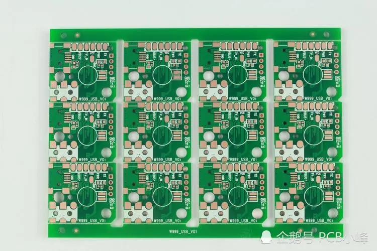
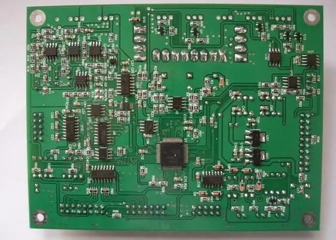
The integrated circuit board is a carrier for loading integrated circuits. But I often take integrated circuits with me. The integrated circuit board is mainly composed of silica gel, so it is generally green.
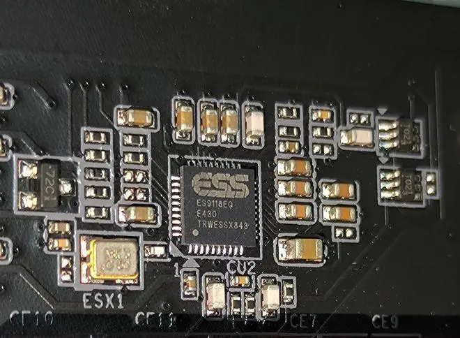
The integrated circuit board adopts the semiconductor manufacturing process to make many transistors, resistors, capacitors and other components on a small single silicon chip, and combines the components into a complete electronic circuit according to the method of multi-layer wiring or tunnel wiring. It is represented in the circuit by the letter "IC" (also with the character symbol "N", etc.).
The integrated circuit board
classification
By functional structure
The integrated circuit board can be divided into analog integrated circuit board and digital integrated circuit board according to its different functions and structures.
Analog is used to generate, amplify and process various analog signals (referring to signals whose amplitude changes with the time border, such as audio signals of semiconductor radios, tape signals of video recorders, etc.), while digital is used to generate, amplify and process various digital signals (referring to signals with discrete values in time and amplitude, such as audio signals and video signals of VCD and DVD playback).
According to the manufacturing process
It can be divided into semiconductor and thin film according to the manufacturing process.
Films are also classified as thick films and thin films.
According to the level of integration
According to the level of integration, it can be divided into small scale, medium scale, large scale and super large scale.
Different by conductive type
According to the conductive type, it can be divided into bipolar type and unipolar type.
Bipolar PCBs have complex manufacturing process and high power consumption. They represent TTL, ECL, HTL, LST-TL, STTL and other types. Monopole type has simple manufacturing process, low power consumption and is easy to be made into large scale. It represents CMOS, NMOS, PMOS and other types.
By use
It can be divided into TV sets according to its use. Audio, DVD player, video recorder, computer (microcomputer), electronic organ, communication, camera, remote control, language, alarm and various special purposes.
TV sets include line and field scanning, medium playback, accompanying sound, color decoding, AV/TV conversion, switching power supply, remote control, voice decoding, picture in picture processing, microprocessor (CPU), memory, etc.
Audio includes AM/FM high and intermediate frequency circuit, stereo decoding circuit, audio pre amplifier circuit, audio operational amplifier, audio power amplifier, surround sound processing, level drive, electronic volume control, delayed reverberation, electronic switch, etc.
DVD player is used for system control, video coding, MPEG decoding, audio signal processing, audio effect, RF signal processing, digital signal processing, servo, motor drive, etc.
VCR is used for system control, servo, drive, audio processing and video processing.
Production process
1. Print the circuit board. Print the printed circuit board with transfer paper. Note that the sliding side faces you. Generally, two circuit boards are printed, that is, two circuit boards are printed on one sheet of paper. Select the PCB with the best printing effect.
2. Cut the copper clad plate and use the photo sensitive plate to make the whole process diagram of the circuit board. The copper clad plate, that is, the circuit board with copper film on both sides, is cut into the size of the circuit board, not too large, to save materials.
3. Pretreatment of copper clad laminate. Polish the oxide layer on the surface of the CCL with fine sandpaper to ensure that the carbon powder on the thermal transfer paper can be firmly printed on the CCL when transferring the circuit board. The polished standard is that the board surface is bright without obvious stains.
4. Transfer circuit board. Cut the printed circuit board to an appropriate size, paste the printed side of the circuit board on the copper clad plate, and put the copper clad plate into the heat transfer machine after alignment. Make sure that the transfer paper is not misplaced when putting it in. Generally speaking, after 2-3 times of transfer, the circuit board can be firmly transferred to the copper clad laminate. The heat transfer machine has been preheated in advance, and the temperature is set at 160-200 ℃. Due to the high temperature, pay attention to safety during operation!
5. Corrosion circuit board reflow welder. First, check whether the circuit board is completely transferred. If there are a few places that are not transferred well, use a black oily pen to repair them. Then it can be corroded. When the exposed copper film on the circuit board is completely corroded, take the circuit board out of the corrosion solution and clean it, so that a circuit board can be corroded. The corrosive solution consists of concentrated hydrochloric acid, concentrated hydrogen peroxide and water, with a ratio of 1:2:3. When preparing the corrosive solution, drain water first, and then add concentrated hydrochloric acid and concentrated hydrogen peroxide. If the concentrated hydrochloric acid, concentrated hydrogen peroxide or corrosive solution accidentally splashes on the skin or clothing during operation, clean it with clean water in time. As strong corrosive solution is required, be careful during operation
6. PCB drilling. PCB components are to be inserted on the circuit board, so it is necessary to drill holes on the circuit board. Different drill needles are selected according to the thickness of the pins of the electronic components. When using the drill to drill holes, the circuit board must be kept steady. The drill cannot be operated too slowly. It is relatively simple to operate the drill, and it can be done well as long as you are careful. Please carefully watch the operator's operation.
7. PCB pretreatment. After drilling, polish the ink powder on the circuit board with fine sandpaper, and clean the circuit board with clean water. After the water is dry, apply rosin perfume on the side of the circuit with only a thin layer, not only to prevent the circuit from being oxidized, but also rosin is a good flux. Generally speaking, the rosin perfume on the surface of the circuit board will solidify within 24 hours. To speed up the rosin solidification, we use a hot air machine and a hot wire circuit board, and the rosin can solidify in 2-3 minutes. The temperature of the hot air blower is as high as 300 degrees. When using it, the air outlet should not be oriented towards combustibles, people and small animals. Safety is the first requirement!
8. Solder PCB components. After welding the electronic components on the plate, power on, function realization and production are completed.


Just upload Gerber files, BOM files and design files, and the KINGFORD team will provide a complete quotation within 24h.