
Professional PCB manufacturing and assembly
Building 6, Zone 3, Yuekang Road,Bao'an District, Shenzhen, China
+86-13410863085Mon.-Sat.08:00-20:00

PCB board tips for reducing signal coupling during RF design
There are many guidelines for RF circuit boarddesign, which can and should not be followed and ignored However, when it comes to actual design, the real trick is how to compromise these standards and laws when they cannot be implemented accurately due to various design constraints Of course, there are many important RF design topics worth discussing, including impedance and impedance matching, insulating materials and laminates, wavelength and standing wave. However, this paper will focus on various issues related to RF board zoning design Today's mobile phone design integrates everything in a variety of ways, which is bad for RF board design The industry is now very competitive, and everyone is looking for ways to integrate multiple functions with size and cost By analogy, digital and RF circuits are tightly packed together, and there is very little space to separate their problem areas. Considering the cost, the number of layers is usually reduced Surprisingly, a multi-purpose chip can integrate multiple functions on a very small chip. The pins connecting to the outside world are so closely arranged that RF. If, by analogy, digital signals are very close, they are usually independent of electricity Power distribution may be a nightmare for designers. Different parts of the circuit can be used in different times according to needs. Software controlled switches are used to extend battery life This means that your phone may require 5 or 6 working power supplies
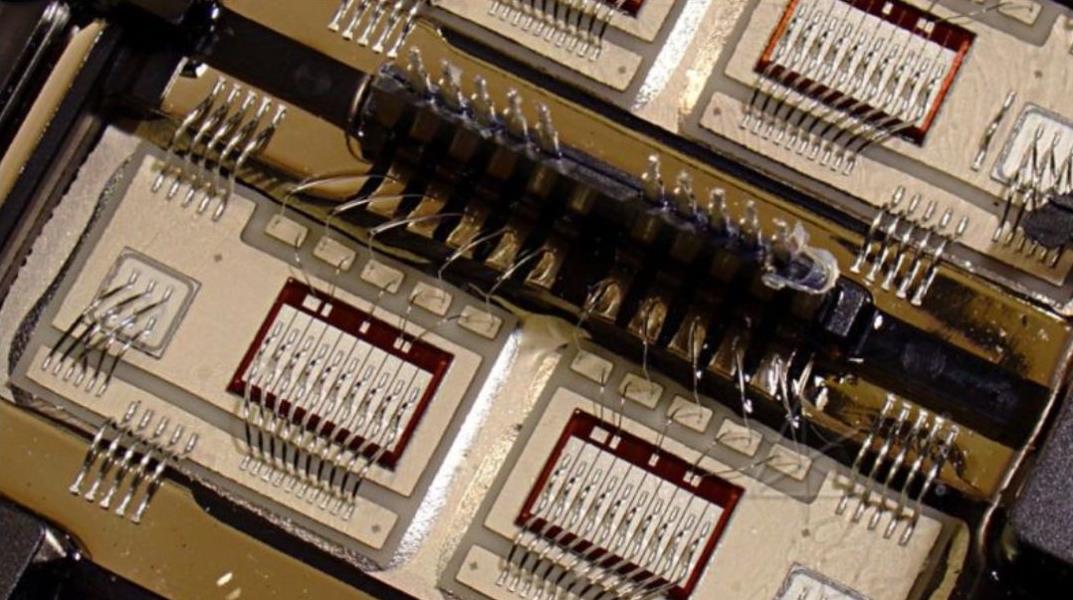
PCB board

RF Layout Concept
When designing the RF layout, we must give priority to several general principles: isolate the high power RF amplifier (HPA) from the low noise amplifier (LNA) as much as possible. In short, keep the high power RF transmitting circuit away from the low power RF receiving circuit. If your PCB has a lot of physical space, you can easily do this, but usually, because there are many components and less space on the PCB, this is usually impossible. You can place them on both sides of the PCB board, or let them work alternately instead of simultaneously. High power circuits may sometimes include RF buffers and voltage controlled oscillators (VCOs). Make sure that at least one of the high power areas on the PCB without via is completely grounded. Of course, the more copper, the better. Later, we will discuss how to break this design principle as needed and how to avoid the problems arising therefrom. Decoupling the chip and the power supply is also extremely important, and several methods to achieve this principle will be discussed later. RF output usually needs to be far away from RF input, which will be discussed in detail later. Sensitive analog signals should be as far away from high-speed digital and RF signals as possible.
How to divide?
Design partitions can be decomposed into physical partitions and power partitions. Physical zoning mainly involves component placement, orientation, mask and other issues; The power partition can be further divided into distribution partition, RF tracking partition, sensitive circuit and signal partition and grounding partition. First, we will discuss the physical partition problem. Component placement is the key to RF design. An effective technology is to first fix the components on the RF path, and adjust its direction to minimize the length of the RF path, keep the input away from the output, and separate the components as much as possible. Power circuit and low power circuit. An effective circuit board stacking method is to lay the main ground plane (main ground plane) on the second layer below the surface layer, and run RF lines on the surface layer as much as possible. Reducing the size of the through-hole on the RF path can not only reduce the path inductance, but also reduce the ghost solder joints on the main ground, and reduce the chance of RF energy leakage to other areas in the stack. In physical space, linear circuits such as multistage amplifiers are usually enough to isolate multiple RF areas from each other, but duplexers, mixers, and if amplifiers/mixers always have multiple RF/IF, signals will interfere with each other. Therefore, care must be taken to minimize this impact. RF and IF traces should be crossed as much as possible, and a grounding space should be left between them as much as possible. Correct RF wiring is very important to the performance of the entire PCB, which is why component placement usually takes up most of the time in the design of mobile phone PCB. On the cellular telephone PCB, it is usually possible to place the low noise amplifier circuit on one side of the PCB and the high power amplifier on the other side, and finally connect them to the RF side and baseband processing at the same location through the duplexer on the equipment antenna. Some techniques are required to ensure that through vias do not transfer RF energy from one side of the circuit board to the other. A common technology is to use blind vias on both sides. By arranging through vias in the area free from RF interference on both sides of the PCB, the harmful effects of through vias can be minimized.
Sometimes it is impossible to ensure adequate isolation between multiple circuit blocks. In this case, metal masks must be considered to mask the RF energy in the RF area. However, metal masks also have problems, such as their own costs and assembly costs are very expensive; Irregular metal masks are difficult to ensure high accuracy in the manufacturing process, and rectangular or square metal masks limit the layout of components; The metal mask is unfavorable to component replacement and fault location; Because the metal mask must be welded to the ground and must be kept at a proper distance from the components, it takes up valuable PCB space. It is important to ensure the integrity of the mask as much as possible. The digital signal line entering the metal mask cover should be as deep as possible into the inner layer, and the PCB board below the wiring layer is the ground plane. The RF signal line can be led out from the small gap at the bottom of the metal mask and the wiring layer at the grounding gap, but it should be distributed around the gap as much as possible. The grounding on different layers can be connected together through multiple through holes. Despite the above problems, metal masks are very effective and are usually the solution to isolate critical circuits. In addition, the proper and effective decoupling of the chip power supply is also very important. Many RF chips with integrated linear circuits are very sensitive to power supply noise. Generally, each chip needs at most four capacitors and one isolation inductor to ensure that all power supply noise is filtered.
The value of capacitor is usually determined by its self resonant frequency and low lead inductance, and the value of C4 is selected accordingly. The values of C3 and C2 are relatively large due to their own pin inductance. This RF decoupling effect is small, but it is more suitable for filtering low-frequency noise signals. Inductor L1 prevents RF signals from being coupled from the power cord to the chip. Please remember that all traces are potential antennas, which can receive and transmit RF signals. It is also necessary to isolate the induced RF signals from key circuits. The physical location of these decoupled components is also often critical. The layout principle of these important components is that C4 should be as close to IC pin as possible and grounded, C3 must be close to C4, C2 must be close to C3, and IC pin must be close to C4. The connection track should be as short as possible, and the grounding terminal of these components (especially C4) should normally be connected to the chip's grounding pin through the next grounding plane. The vias connecting components to the ground plane should be as close to the component pads on the PCB as possible. The blind hole on the bonding pad is used to reduce the inductance of the connecting wire, and the electrical induction is close to C1. Integrated circuits or amplifiers usually have open drain outputs, which require pulling up inductors to provide high impedance RF loads and low impedance DC power supplies. The same principle applies to the decoupling of the power supply at the inductor side. Some chips require multiple power supplies to work. Remember that you may need two or three groups of capacitors and inductors to decouple them. If there is not enough space around the chip, this may cause some problems. Please remember that inductors are rarely connected in parallel, because this will form an air core transformer and generate interference signals. The distance between them must be at least as far as the height of one of the equipment, or at right angles, to reduce its mutual inductance.
The principle of electrical partition is usually the same as that of physical partition, but there are also some other factors involved. Some parts of modern mobile phones work at different voltages and are controlled by software to extend battery life. This means that the phone needs to run multiple power supplies, which creates more isolation problems. The power supply is usually introduced from the connector and is immediately decoupled to filter out any noise outside the circuit board before being distributed through a set of switches or voltage regulators. Most circuits in mobile phones have relatively small DC current. This track width is usually not a problem, but you must run a separate high current track as wide as possible to power the high power amplifier to minimize the transmission voltage. To avoid excessive current loss, multiple vias are required to transfer current from one layer to another. In addition, if the high power amplifier is not fully decoupled at its power supply pin, the high power noise will radiate to the entire circuit board and cause various problems. The grounding of high power amplifier is very important, and usually requires a metal mask. In most cases, it is also important to ensure that the RF output is kept away from the RF input. This also applies to amplifiers, buffers, and filters. In the worst case, if the output of the amplifier and buffer responds to its input with appropriate phase and amplitude, the amplifier and buffer may self oscillate. In any case, they will work stably at any temperature and voltage. In fact, they may become unstable and add noise and intermodulation to the RF signal.
If the RF signal line must be looped back from the input to the output of the filter, it may seriously damage the band-pass characteristics of the filter. In order to obtain good isolation between input and output, first, ground must be placed around the filter. Second, ground should be placed in the lower area of the filter and connected to the main ground around the filter. It is also a good idea to keep the signal wires that need to pass through the filter as far away from the filter pins as possible. In addition, be careful to ground anywhere on the circuit board, or you may inadvertently introduce a coupling channel that you do not want to happen. This grounding method is detailed in Figure 3. Sometimes, single ended or balanced RF signal lines can be selected. The same principles for cross interference and EMC/EMI apply here. If properly wired, balanced RF signal lines can reduce noise and cross interference, but their impedance is usually very high, and reasonable line width should be maintained to obtain impedance matching with source, track and load. The actual wiring may be difficult. Buffer can be used to improve isolation, because it can divide the same signal into two parts and use it to drive different circuits, especially when the local oscillator may need buffer to drive multiple mixers. When the mixer reaches common mode isolation at RF frequency, it will not work properly. The buffer can well isolate the impedance changes under different frequencies, so that the circuits will not interfere with each other. Buffers are very helpful in design. They can be placed behind the circuit to be driven. Considering that the high power output track is very short, because the input signal level of the buffer is relatively low, they are not easily affected by other circuits on the board. A circuit that causes interference. There are many very sensitive signal lines and control lines that need special attention, but they are beyond the scope of this article. I will only briefly discuss them here, and will not describe them in detail.
Voltage controlled oscillators (VCOs) convert varying voltages into varying frequencies, which is used for high-speed channel switching. However, they also convert a small amount of noise in the control voltage into a small frequency change, thus adding noise to the RF signal. Usually, after that, you can no longer remove noise from the RF output signal. So where is the difficulty? First, the expected bandwidth of the control line can be between DC and 2MHz, and it is almost impossible to filter in such a wide frequency band to remove noise; Secondly, the VCO control circuit is usually a part of the echo loop of the control frequency. In many cases, noise may be everywhere. Therefore, care must be taken to handle the VCO control circuit. Ensure that the ground below the RF trace is secure, that all components are securely connected to the main ground, and that they are isolated from other traces that may introduce noise. In addition, ensure that the power supply of the voltage controlled oscillator is fully decoupled, because the RF output of the voltage controlled oscillator is often at a relatively high level, and the output signal of the voltage controlled oscillator is easy to interfere with other circuits. Therefore, special attention must be paid to the voltage controlled oscillator. In fact, VCOs are usually placed at the end of the RF area, sometimes requiring a metal mask.
Resonant circuit (one for transmitter and the other for receiver) is related to voltage controlled oscillator, but has its own characteristics. In short, the resonant circuit is a parallel resonant circuit with a capacitor diode, which helps to set the operating frequency of the voltage controlled oscillator and modulate voice or data to the RF signal. All VCO design principles are also applicable to resonant circuits. Resonant circuits are usually very sensitive to noise because they have a large number of components, are widely distributed on circuit boards, and usually operate at very high RF frequencies. The signal is usually arranged on the adjacent pins of the chip, but these signal pins need to work with relatively large inductors and capacitors, which in turn requires that these inductors and capacitors be closely placed together and connected back to the noise sensitive control loop. It is not easy to do this. Automatic gain control (AGC) amplifier is also a place prone to problems. There will be an AGC amplifier in both the transmitting and receiving circuits. Generally, AGC amplifiers can effectively filter out noise, but the ability of mobile phones to handle the rapid change of transmission and reception signal strength requires that AGC circuits have a fairly wide bandwidth, which makes it easy for AGC amplifiers on some key circuits to introduce noise. When designing AGC circuits, good analog circuit design technology must be followed, which is related to very short input pins of operational amplifiers and very short echo paths, both of which must be far away from RF, IF or high-speed digital signal tracks. In addition, good grounding is essential, and the power supply of the chip must be well decoupled. If you have to lay a long wire at the input or output end, it is at the output end. The impedance of the output end is usually much lower and it is not easy to generate induced noise. Generally, the higher the signal level, the easier it is to introduce noise into other circuits. In all PCB designs, it is a general principle to keep digital circuits away from analog circuits as much as possible, which is also applicable to RF PCB design. The common analogy grounding is usually as important as the grounding used for shielding and separating signal lines. The problem is that without foresight and careful planning, it is almost impossible to do this every time. Recall that in the early stage of design, careful planning, deliberate component placement and thorough placement evaluation are very important, because unintentional design changes may lead to the need to rebuild a nearly completed design. Anyway, the serious consequences of such negligence are not good for your personal career development. In addition, keep RF lines away from analog lines and some very critical digital signals. All RF traces, pads and components shall be filled with grounding copper as much as possible and connected to the main grounding as much as possible. Micro through-hole building boards such as bread boards are very useful in the RF circuit development stage. If you choose a building board, you can use any number of through-hole for free. Otherwise, drilling holes on ordinary PCBs will increase the development cost, which will increase the cost in mass production.

High speed PCB board analogy for power integrity
Nov 04,2022


Just upload Gerber files, BOM files and design files, and the KINGFORD team will provide a complete quotation within 24h.