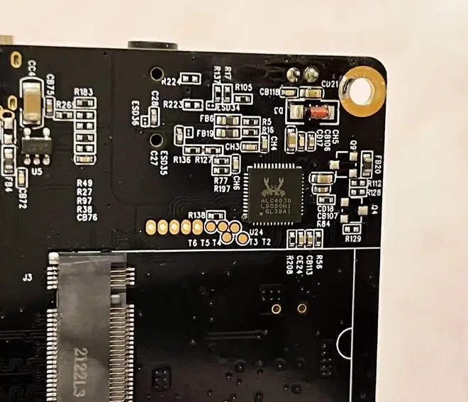
Pcb factory: introduction of varistor characteristics and related physical quantities
The circuit board manufacturer and circuit board designer explain the characteristics of varistor and related physical quantities
Characteristics of varistor
The voltage and current of varistors do not obey Ohm's law, so they have a special nonlinear relationship. When the voltage applied at both ends is lower than the nominal rated voltage, the resistance of the varistor is close to infinity, and there is almost no current flowing through the varistor; When the voltage applied at both ends is slightly higher than the nominal rated voltage, the varistor will break down and conduct quickly, and change from high resistance state to low resistance state, and the working current will also increase sharply; When the applied voltage at both ends is lower than the nominal rated voltage, the varistor will return to the high resistance state; When the voltage applied at both ends exceeds the maximum limit voltage value, the varistor will be completely broken down and damaged, and can no longer recover by itself.

Key parameters of varistor
Voltage sensitive voltage: voltage sensitive is breakdown voltage or threshold voltage. It is generally believed that when the temperature is 20 degrees and there is 1mA current flowing through the varistor, the corresponding voltage value is applied to both ends of the varistor. The varistor voltage is the nonlinear starting voltage at the inflection point of the I-U curve of the varistor, and it is the nonlinear voltage that determines the rated voltage of the varistor. In order to ensure that the circuit is within the normal working range and the varistor works normally, the voltage value of the varistor must be greater than the maximum rated working voltage of the protected circuit.
Maximum limiting voltage: the maximum limiting voltage refers to the maximum voltage that can be borne by both ends of the varistor. The popular explanation is that when the surge voltage exceeds the voltage sensitive voltage, the highest peak voltage measured at both ends of the varistor is also called the maximum clamping voltage. In order to ensure that the protected circuit will not be damaged, when selecting the varistor, the maximum limiting voltage of the varistor must be less than the rated maximum working voltage of the circuit (if multi-level protection is adopted, it can be considered separately).
Through current capacity: the through current capacity, also known as through current, refers to the maximum pulse (peak) current value allowed to pass through the varistor under specified conditions (applying standard impulse current at specified time interval and times).
Usually, the flow rate given by the product is the maximum current that the product can withstand when conducting pulse test according to the waveform, impact times and gap time given in the product standard. The number of shocks that the product can withstand is a function of the waveform, amplitude and gap time. The number of shocks can be doubled when the current waveform amplitude decreases by 50%. Therefore, in practical applications, the surge current absorbed by the varistor should be greater than the maximum flow of the product.
The surge current amplitude absorbed by the varistor shall be less than the maximum flow of the product given in the manual. However, from the perspective of protection effect, it is required to select a larger flow rate. In many cases, the actual flow is difficult to calculate accurately, so 2-20kA products are selected. If the flow capacity of the product at hand cannot meet the use requirements, several individual varistors can be used in parallel. The voltage of the varistor after parallel connection will not change, and the flow capacity is the sum of the values of each individual varistor. It is required that the voltage current characteristics of the parallel varistors should be the same as much as possible, otherwise it is easy to cause uneven shunt and damage the varistors.
Voltage ratio: the voltage ratio refers to the ratio between the voltage value generated when the current of the varistor is 1mA and the voltage value generated when the current of the varistor is 0.1mA.
Residual voltage ratio: when the current flowing through the varistor is a certain value, the voltage generated at its two ends is called the residual voltage. Residual voltage ratio is the ratio of residual voltage to nominal voltage.
Leakage current: also known as waiting current, leakage current refers to the current flowing through the varistor at the specified temperature and maximum DC voltage. The smaller the leakage current, the better. For the leakage current, it should be emphasized that it must be stable, and it is not allowed to increase automatically during operation. Once the leakage current automatically increases, it should be eliminated immediately, because the instability of the leakage current is the direct reason for accelerating the aging of the lightning protector and the explosion of the lightning protector. Therefore, when selecting the leakage current parameter, the smaller the better cannot be blindly pursued. As long as the leakage current value is within the allowable range of the power grid, the lightning arrester with a relatively large leakage current value is selected, which is more stable.
The circuit board manufacturer and circuit board designer explain the characteristics of varistor and related physical quantities


