
Professional PCB manufacturing and assembly
Building 6, Zone 3, Yuekang Road,Bao'an District, Shenzhen, China
+86-13410863085Mon.-Sat.08:00-20:00

With the popularity of SMT lead-free process technology, the demand for PCB substrate is becoming higher and higher. To improve the performance of the circuit board can be started from the design of the circuit board, then the programming of the circuit board is very important.
No matter which programmable device manufacturer's website you visit, you'll find that programming devices on a circuit board is a feature they advertise everywhere. We call it in-system programming (ISP), and people have been using it for years. ISP technology can speed up code debugging, and finally complete the design of new products, ready for manufacturing. There are practical advantages to using ISP technology in production. ISP can reduce the cost of programming the device. Using ISP technology increases flexibility, i.e. the ability to reprogram on the production line, or multistep programming on the circuit board, without having to reverse repair or take the device off. ISP technology eliminates the need to keep track of the inventory of pre-programmed devices. Once the board is ISP capable, it can be upgraded or serviced on site. How can engineers optimize PCB design to implement ISP on the production line? There are a variety of designs that can simplify this transition.
1. Figure out which parts of the circuit board are programmable. Not all the components on the circuit board can be programmed in the system. For example, parallel devices are usually not allowed to do this. For programmable devices, the ISP's serial programming capability is essential in order to maintain the flexibility of the design.
2. Check the programming technical specifications for each device to determine which pins are required. This information can be obtained from the device manufacturer or downloaded online. In addition, field application engineers can provide device and design support and are a great resource.
3. Connect the programming pins to use the pins on the control board. Verify that the programmable pins are connected to the connectors or test points on the circuit board in this design. These are required for in-circuit testers (ICTs) or ISP programmers used in production.
4. Avoid contention. Make sure that the signal required by the ISP is not connected to any other hardware that might conflict with the programmer. Look at the load on the line. Some processors can drive light-emitting diodes (leds) directly, but most programmers don't. This can be a problem if the input/output is shared. Please pay attention to monitor timer or reset signal generator. If a random signal is emitted by the monitor timer or reset signal generator, then the device may be incorrectly programmed.
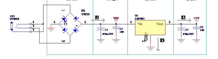
5. Determine how a programmable device is powered during manufacturing. The target circuit board must be powered to enable programming in the system.
We also need to determine the following questions:
(1) What kind of voltage is needed? In programming mode, components typically require a different voltage range than they do in normal operating mode. If the voltage is high during programming, it must be ensured that this higher voltage will not cause damage to other components.
(2) Some devices must be tested at high and low levels to ensure that the programming of the devices is correct. If so, the range of voltage must be specified. Check the reset generator first, if there is one, as it may attempt to reset the device while performing a low voltage test.
(3) If the device requires a VPP voltage, supply the VPP voltage on the circuit board or use a separate power supply to power it during production. Processors that require VPP voltage will share this voltage with the digital input/output line. Please make sure that other circuits connected to the VPP can operate at higher voltages.
(4) Is a monitor needed to see if the voltage is within the technical specifications of the device? Please make sure that the safety device is effective and can keep these power sources within a safe range.
6. Figure out what kind of device to use for programming, as well as design. During the test phase, if the board is programmed on a test fixture, pins can be attached via a pin bed. Alternatively, if you need to use a rack tester and run a specialized test program, it is best to use a connector on the side of the printed circuit board or a cable connection.
7. Come up with creative ways to track information. Adding configuration-specific data to the back of the line is becoming more common. Programmable devices can be made into "smart" devices for as long as they are useful. Adding product-related information to a product, such as serial number, MAC address, or manufacturing data, makes the product more useful, easier to maintain and upgrade, or easier to provide a warranty, and helps the manufacturer gather useful information over the life of the product. Many "smart" products have this tracking capability by adding a simple and inexpensive EEPROM that is programmed with production line or field data.
Well-designed circuits that fit into the final product can also pose obstacles to ISP implementation during the production process. Therefore, the board needs to be modified to make it best fit the ISP on the production line and finally get a good circuit board.


Just upload Gerber files, BOM files and design files, and the KINGFORD team will provide a complete quotation within 24h.