
Professional PCB manufacturing and assembly
Building 6, Zone 3, Yuekang Road,Bao'an District, Shenzhen, China
+86-13410863085Mon.-Sat.08:00-20:00

Usually, a complete machine is composed of several printed circuit boards, printed circuit boards can be large or small. The circuits contained on each printed board are often plotted on a circuit diagram. Therefore, a whole machine circuit diagram is often composed of a number of plate circuit diagram, read each plate circuit diagram, you can read the whole machine circuit diagram, each plate circuit diagram includes one or several circuit systems, large plate circuit diagram is almost as complex as the ordinary small and medium-sized screen TV circuit diagram. Although the circuit is more complex, a variety of plate circuit to complete different functions, but they have rules to follow, can be in accordance with a certain method to gather to read.
In order to read the circuit diagram less detours, should use the correct reading method and steps. Usually take the outer perimeter, from the outside in method. Adopting the method of internal and external combination, forward and backward connection, step by step breakthrough, can read all the circuit diagram smoothly. The specific methods and steps of looking at the picture can be summed up in three sentences and three steps: starting from the periphery and choosing the entrance; Open the gap, contact before and after; Difficulty analysis, put in the last.
1, intuitive start, choose a good entrance
That is to say, first look at the most intuitive, easy-to-read components and circuits at the edge of the circuit, as the entrance to read the diagram. A group of circuits or blocks can be found from these peripheral recognizables moving inward along the signal line (possibly in the opposite direction of the signal flow).
Open the gap, connect back and forth
There are some weaknesses in any circuit diagram. The simplicity and difficulty of each part of the circuit are always somewhat different, or the graphics and symbols of some components are different from those of general components. These places are the internal weak link and easy link of reading the diagram, and they can be used as the internal breakthrough of reading the diagram. These places can be selected as the breakthrough to read the picture, open the gap, can quickly forward, after, left, right contact, and with the first step method, you can read many circuits.
There are always many familiar links in the circuit diagram, grasp it can quickly open the gap to see the map, to the depth of development. The most intuitive and easy to read internal link is the integrated circuit, especially those large-scale integrated circuit, their leading feet are more than 40, more than 100, very eye-catching in the diagram, the plotter also often placed them in the center or obvious position of the circuit diagram. Then, with these integrated circuits as the center of expansion, can find many circuits. The integrated circuit as an internal breakthrough needs to have a prerequisite, must know the specific model of these integrated circuits, know the main function of the model integrated circuit, familiar with the name and use of its main outlet foot, otherwise it will bring a lot of inconvenience to read the diagram. Sometimes, we have been familiar with most integrated circuits, but not familiar with some individual integrated circuits. According to the block diagram and the relationship before and after, we can guess the function of the unknown integrated circuit.
Circuit diagram there are some easy to read, easy to remember content, can also be used as a breakthrough inside the circuit. For example, the Chinese characters, foreign letters or abbreviations marked in the figure, some important and easy to read graphic symbols of components, some adjustable resistors or potentiometers, etc. In order to be able to use these breakthroughs conveniently and smoothly, the reader should be familiar with the physical meaning of various foreign letters and abbreviations, have a certain foreign language foundation (generally English), should be familiar with some professional terms and abbreviations often used by audio-visual equipment; Be familiar with the functions, parameters and indicators of these components. A wide range of knowledge is conducive to reading pictures, and you should consciously memorize some useful common sense.
3, difficulty analysis, put in the last
After the above two steps reading process, most of the circuit diagram can be understood. However, there will be some remaining parts of the circuit is not understood or not well understood. The third step can be dedicated to eliminating difficult points. This is the hard part of looking at the picture, and this is the last step. Readers can break through difficult circuits through various methods or means.
In the practical circuit diagram, it is difficult to understand the place is often manifested in two places, one is the signal flow processing process inside some integrated circuits, because these contents can not understand, so its external lead foot function can not be understood; The other is some peripheral discrete component circuit, do not understand the purpose of setting the circuit, do not know the signal processing process. For these difficult circuits, according to the machine block diagram, according to the function of each part of the circuit and the interrelation, through logical analysis, test function and signal flow analysis methods, always can understand these difficult circuits.
In fact, the circuit diagram for reading and use of information is very much, with the reader's synthesis, analysis, research, must be able to understand the whole picture. Each person's actual situation is different, the way to look at the picture and judge may be slightly different, the steps of looking at the picture are not invariable. Electronic technology develops very fast, manufacturers often develop new circuit or new function circuit, even the circuit program is more strange. On the basis of the above basic ideas, we can flexibly complete the work of reading pictures.
Understand the circuit board routing method analysis
For beginners in electronic technology, mastering basic circuit principle, function characteristics and detection of components, how to analyze schematic diagram, look at PCB, welding technology of components and common maintenance methods are all basic skills, which need to be mastered well. Here is how to look at PCB, hope to help beginners.
The component layout on the PCB is very different from the schematic diagram, which can make beginners feel "complicated" and difficult to see the lines.

How to know the components on PCB.
1. In the actual analysis of PCB, first of all, according to its appearance, see what components this component like seen before, but this accuracy is not high, you have to rely on usually see more, see enough to know.
2. Secondly, combined with the printing of components themselves to identify, generally speaking, printing describes some parameters or models, of course, there are manufacturers of batch number, version number and other attributes, some even through what international certification symbols also have, this method also depends on the peacetime understanding of components, parameters and so on.
For example, a triode type device, marked C1815 is a low-power low-frequency NPN type triode; Marked TL431 is integrated voltage regulator IC; If 13001 is marked, it is a small power switch tube, which can be used in small small power chargers.
Again, you can take apart the components to see the internals.
A certain type, series of components, with the same or similar structural characteristics, much dismantled, the internal structure of the components, the working principle is more familiar. You can take apart as many components as possible to further improve your basic component knowledge.
3. If the component is on the PCB, it can be determined according to the component symbol and screen printing on the PCB. If you label it R12, that's the resistor, and it's numbered 12 in the circuit. X, Y and Z can all represent crystal vibration. At the same time, the function of components can be judged according to the circuit in which they are located, so as to analyze which kind of components they belong to. This requires you to be familiar with the basic circuit.
Due to the reasons of technology, production and manufacturer, the same component may have different shapes, structures and materials, which will bring some difficulties for you to analyze PCB board. If conditions permit, you can go to specialized electronic component stores and electronic cities to have a look.
Circuit board processing how to choose PCB board
Jan 25,2023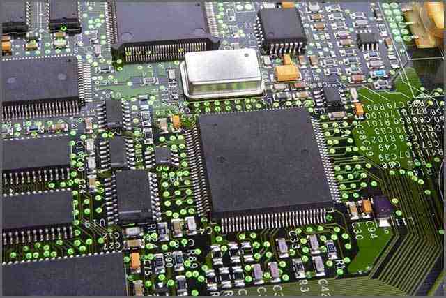


Just upload Gerber files, BOM files and design files, and the KINGFORD team will provide a complete quotation within 24h.