
Professional PCB manufacturing and assembly
Building 6, Zone 3, Yuekang Road,Bao'an District, Shenzhen, China
+86-13410863085Mon.-Sat.08:00-20:00

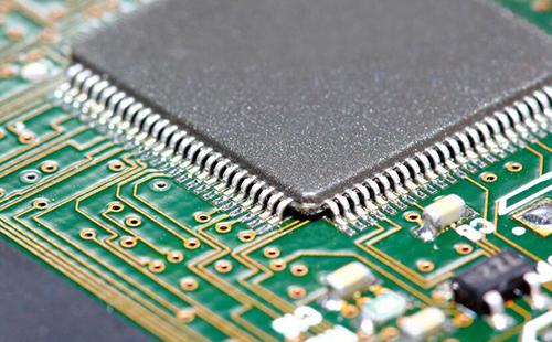
PCBA patch processing process is very complex, including PCB board manufacturing process, component procurement and inspection, SMT patch assembly, DIP plug-in, PCBA testing and other important processes. PCBA functional test refers to a test method that provides a simulated operating environment for the test target board and makes it work in various design states, so as to obtain parameters of each state to verify the function of PCBA. Simply put, it is to load the appropriate excitation to the PCBA and measure whether the output response meets the requirements. Generally refers to the PCBA function test after the actual circuit board is powered on.
PCBA functional test content voltage, current, power, power factor, frequency, duty ratio, position measurement and other functional parameters measurement. PCBA functional test includes: General section:

1: Power part test - power supply is working properly, test voltage at each point - use comparator or other
2: indicates whether the port (interface) test is Short or Open, resulting in an exception.
3: IC integrated circuit module I/O read and write functional tests - Flash, EEPROM, CPU, SDRAM, Flash IC
4: Special function test (different circuit board requirements are inconsistent)- such as with infrared ray, need external receiver
PCBA functional testing involves analog, digital, memory, RF, and power circuits, usually with different testing strategies. Testing includes a lot of actual significant functional pathways and structural verification (to make sure there are no hardware errors) to make up for missing parts of the previous testing process. This requires a large number of analog/digital incentives to be continuously applied to the PCBA, while monitoring the same number of analog/digital responses and fully controlling their execution. PCBA functional testing systems and devices come in many forms, each with advantages and disadvantages in terms of cost, time, effectiveness, and maintainability.
PCBA functional test equipment
1. Model test system
Theoretically, the easiest way to verify the functionality of a device (a circuit board or module) is to put it in a model system or subsystem like the real thing and see if it works. If it is, we can be pretty sure that it is. If it is not, the technician will test it and try to find out the cause of the failure to guide repair. In practice, however, this plug-in power-on method has many drawbacks and is rarely effective, although it can sometimes be used as a supplement to other test scenarios.
2. Test bed
The test bench is a conventional test environment that includes excitation/response interfaces with the equipment under test, test sequences and controls specified in specific test procedures. Excitation and response are usually provided by standard power supplies and laboratory instruments, special switches, loads, and end-custom electronics such as digital excitation. Here the fixture is a very important part of providing the correct signal path and connectivity to the device under test. In many cases, jigs are basically customized for each application and need to be set up in combination with manual manipulation. Testing procedures and controls are usually carried out manually, sometimes with PC assistance, through written protocols or procedures. The advantages of the testbed being connected to a specific product are relatively low cost, relatively simple equipment, but less flexibility when dealing with multiple products.
3. Special test equipment
In theory, a dedicated test device is a system that automates the operation of the test bench. The heart of the system is usually a computer, controlled by a dedicated bus and some programmable instruments. Speed, performance, availability, cost and other factors affect the choice of instrument bus and structure. Various instruments and general equipment are stacked in one or more vertical cases and then connected to the device under test. With automated processing, setup times, test times, and overall operation are much faster and easier than manual test stands. The STE can be expanded to meet a variety of performance requirements and is typically used in production or repair centers. The most obvious thing about STE is the overall cost: the cost of equipment investment, the cost of operation, and the cost of program development.

4. Automatic test equipment
General Purpose Automated Test Equipment (GPATE, or ATE for short) is a very advanced and flexible solution to meet a variety of product and program testing requirements. System integration, signal connectivity flexibility, value-added hardware and software, test-oriented languages, graphical user interfaces, etc., are the main differences between ATE and STE. In addition to the benefits of fully integrated instruments, ATE also provides better solutions for signal routing and connectivity. The ATE special backplane in most cases includes an analog bus that allows the instrument to connect directly to any pin without complicating the inner and outer leads. This flexibility can often be extended to bring analog and digital channels together, allowing the user to connect digital or analog excitation at any time, and to measure receiver arbitrary pins. The result is not only greatly simplified and reduced costs, but also easier implementation of the test program. According to the different control mode, it can be divided into: manual control PCBA function test, semi-automatic control PCBA function test, fully automatic control PCBA function test.
With the rapid development of science and technology, in order to save production costs and improve production efficiency, some functional tests of PCBA now use fully automatic testing schemes. At present, for the PCBA functional testing of some simple slabs under test, manual or semi-automatic testing schemes are still adopted in order to simplify the design and reduce the production cost.


Just upload Gerber files, BOM files and design files, and the KINGFORD team will provide a complete quotation within 24h.