
Professional PCB manufacturing and assembly
Building 6, Zone 3, Yuekang Road,Bao'an District, Shenzhen, China
+86-13410863085Mon.-Sat.08:00-20:00

Summary of processing difficulties of high-frequency microwave board
Circuit board manufacturing, circuit board design and PCBA processing manufacturers explain the processing difficulties of high-frequency microwave boards
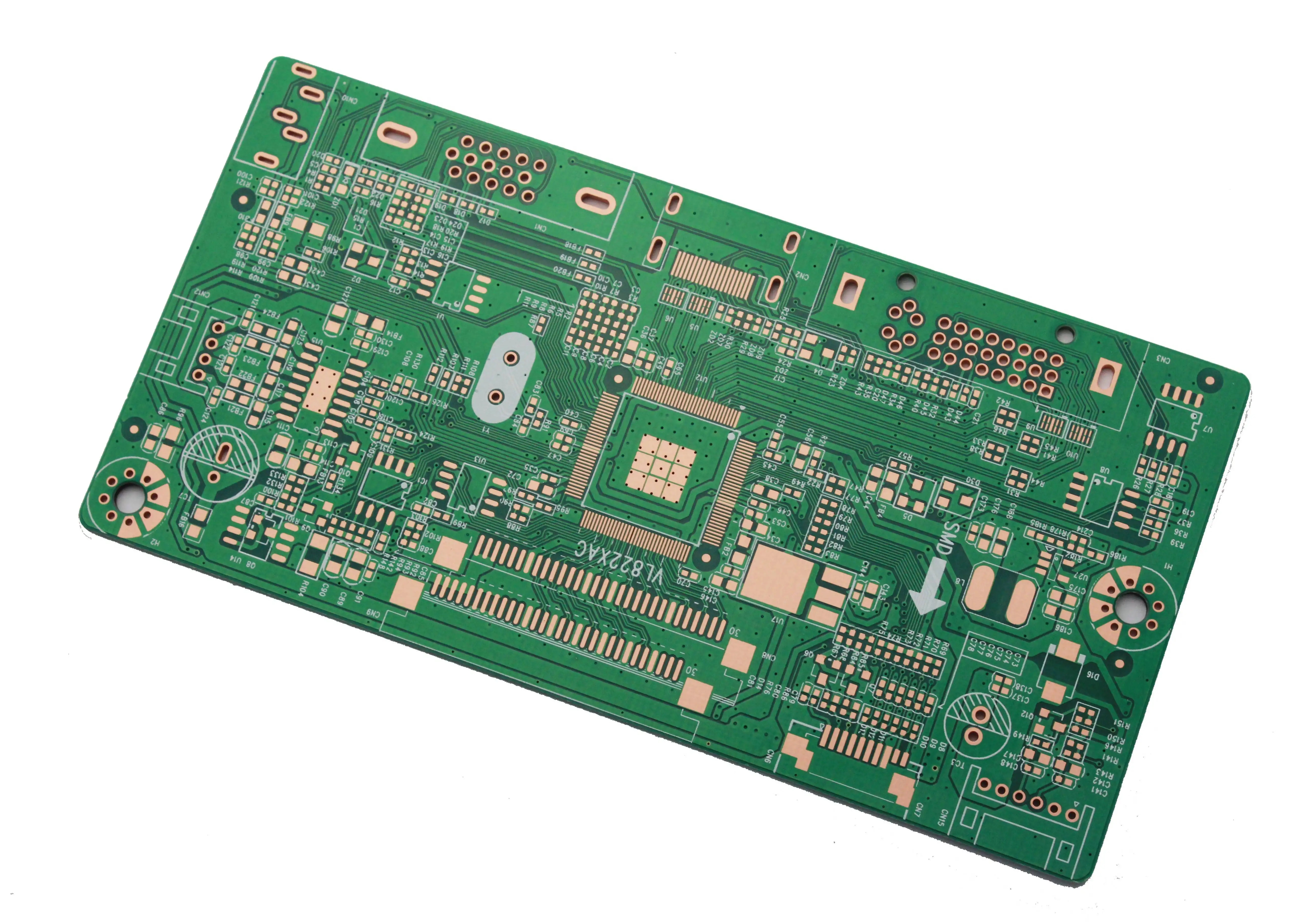
For special PCB with high electromagnetic frequency, generally speaking, high frequency can be defined as frequency above 1GHz. Its physical performance, accuracy and technical parameters are very high, and are commonly used in automotive anti-collision systems, satellite systems, radio systems and other fields. The price is high, usually around 1.8 yuan per square centimeter, about 18000 yuan per square meter.
Whether the design of the short circuit protection function of the driver is perfect is crucial to the safe operation of the power supply. It is necessary to test whether the short-circuit protection function of a driver circuit is perfect before using it.
Based on the physical and chemical characteristics of the high-frequency plate, its processing technology is different from the traditional FR4 process. If it is processed under the same conditions as the conventional epoxy resin glass fiber copper clad plate, qualified products cannot be obtained.
(1) Drilling: the base material is soft, and the number of laminated plates for drilling shall be small. Generally, the thickness of 0.8mm plate shall be two in one; The speed should be slower; To use a new drill bit, the tip angle and thread angle of the drill bit have special requirements.
(2) Print resist welding: after the plate is etched and before the green oil of print resist welding, the plate cannot be polished by roller brush to avoid damaging the base plate. Chemical surface treatment is recommended. To achieve this, it is not easy to make the circuit and copper surface uniform and consistent without grinding the plate, and there is no oxide layer.
(3) Hot air leveling: based on the inherent performance of the fluororesin, the rapid heating of the plate should be avoided as far as possible. Before tin spraying, the preheating treatment should be carried out at 150 ℃ for about 30 minutes, and then tin spraying should be carried out immediately. The temperature of tin cylinder should not exceed 245 ℃, otherwise the adhesion of isolated pads will be affected.
(4) Milling profile: the fluororesin is soft, and the profile of ordinary milling cutter is very burry and uneven, so the profile needs to be milled with a suitable special milling cutter.
(5) Transportation between processes: it cannot be vertically placed, but can only be horizontally placed in the basket separated from paper. It is not allowed to touch the line graphics in the board with your fingers during the whole process. The whole process shall prevent scratches and scratches. Scratches, pinholes, indentations and pits of the lines will affect the signal transmission, and the boards will be rejected.
(6) Etching: side etching, sawtooth and notch shall be strictly controlled, and the line width tolerance shall be strictly controlled ± 0.02mm. Check with a 100x magnifying glass.
(7) Chemical copper deposition: The pretreatment of chemical copper deposition is the most difficult and critical step in manufacturing high-frequency boards. There are many methods for pretreatment of copper deposition, but in summary, there are only two methods that can stabilize the quality and are suitable for mass production:
Method 1: Chemical method: metal sodium plus tetrahydrofuran solution to form tetrahydrofuran complex, so that the surface atoms of polytetrafluoroethylene in the hole are etched to wet the hole. This is a classic and successful method with good effect and stable quality, but it is highly toxic, flammable and dangerous, and needs to be managed by special personnel.
Method 2: Plasma method: The imported special equipment is required to inject carbon tetrafluoride (CF4) or argon (Ar2), nitrogen (N2) and oxygen (O2) between the two high-voltage electrodes under the vacuum environment. The printed board is placed between the two electrodes, and the plasma is formed in the cavity, so as to remove the dirt and dirt in the hole. This method can obtain satisfactory uniform effect, and batch production is feasible. Circuit board manufacturers, circuit board designers and PCBA manufacturers will explain to you the summary of processing difficulties of high-frequency microwave boards.


Just upload Gerber files, BOM files and design files, and the KINGFORD team will provide a complete quotation within 24h.