
Professional PCB manufacturing and assembly
Building 6, Zone 3, Yuekang Road,Bao'an District, Shenzhen, China
+86-13410863085Mon.-Sat.08:00-20:00

Expensive and complex discrete interconnect cables can reduce design reliability, increase design cost and overall design size. Fortunately, there is an alternative to flexible and flex-rigid PCBs. Flexible PCBs provide a cost-effective and convenient solution to your design interconnect requirements, with the added benefit of PCB repeatability and reliability. Discrete interconnects have inherently different conductor orientations, whereas flex PCBs keep all conductors in a specific orientation fixed to each other. This combined consistency allows for accurate modeling and more predictable design of flexible PCB traces. Additionally, the flexible PCB can include gold finger contacts, allowing the edge of the flexible PCB to function as a male portion of the connector and can accommodate high density designs. As such flexible PCBs can be used to replace the vast majority of traditional discrete interconnect solutions, while still allowing for a highly modular design.

In addition to providing an efficient way to design and produce interconnect solutions, flexible PCBs can also accommodate components and form the basis of the entire solution. Using flex PCBs in place of traditional PCBs enables smaller and less traditional PCB designs that can fit in enclosures that would otherwise not be able to accommodate traditional PCBs. Instead of mounting the components to a rigid PCB, you can mount it on a flexible solution and they will conform to the contoured enclosure. Additionally, parts of the flexible PCB can be reinforced with a reinforcing substrate for increased reliability. In the end, flex PCBs help to achieve the lightest solution, since flex PCBs have significantly lower weight per unit area compared to conventional PCBs. Examples of applications that are typically based on flexible PCB solutions include wearables, digital cameras, medical devices, and other small consumer electronics.
Flexible PCBs also have the advantage of being inherently resistant to vibration. They are often used in automotive equipment because of its inherent vibration resistance and are also ideal for electronic equipment with mechanical parts. Therefore, they are widely used in printers, hard disks and keyboards.
Flexible Rigid PCBs are the best among traditional PCBs and flexible solutions. Features a flex-rigid design with built-in interconnect between the two boards. Using flex-rigid solutions, designers can accommodate 3D solutions in one assembly step. Using flexible rigid PCBs instead of traditional PCBs and discrete connections can shorten the assembly time of the final product and ultimately result in a more reliable product. The growth in the use of flex-rigid solutions in recent years is a testament to the practicality offered by flex-rigid solutions.

Using Flexible Rigid PCBs to Produce More Reliable Products
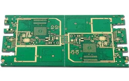
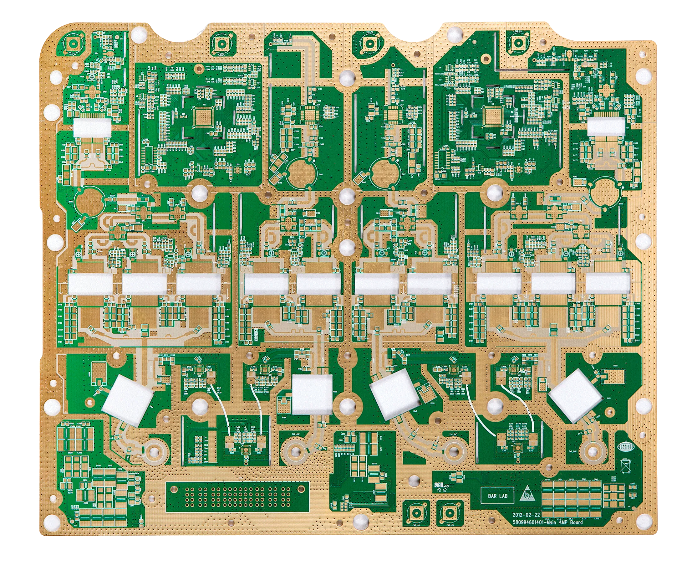
Below are two samples of flexible rigid PCBs fabricated by PCBCart:

Using Flexible Rigid PCBs to Produce More Reliable Products
The design process for flexible or rigid solutions is very similar to traditional PCB boards, with the caveat that the flexible part of the board requires special attention to mechanical quality. Once the 2D layout of the flexible design has been created, it is best to use 3D modeling software to create a simulation of the flexible design, or to create a paper to simulate the design. Use this method to test whether the design meets the mechanical specifications of the flexible substrate. In addition to that, your design does not need to have a bend radius smaller than what the flex PCB allows. Refer to IPC-2223 to determine the minimum bend radius for a particular design.
Other design tips include: Consider staggered traces from one layer to another on the flex circuit to provide a higher level of flexibility. Conductors should always be routed perpendicular to the bend radius for reliability and flexibility. Termination areas shall be reinforced with stiffeners. Masking should be done with a cross-hatched pattern instead of a solid plane. Vias should be kept away from bend areas.
Before sending your design to manufacture, consider that the flex board is bendable during the design process, and that the design board has the highest density on the fabrication board when nested. If bending can be used to achieve a specific size, bend it in the installation, not in the initial design. Finally, using stiffeners with flexible PCBs may be more cost-effective than flex-rigid designs. When you only need fewer layers in your design, it may be more cost effective to use a flex PCB and add stiffeners to critical parts of the board. Flexible rigid solutions should only be considered if your design has very large layer count requirements.
Finally, filling a flex PCB is very similar to filling a rigid PCB. When doing flexible PCB assembly, consider the following tips:
• Bake the flex PCBs for an hour, then fill them to remove any absorbed moisture.
• Secure the flex PCB to a hard surface to provide dimensional stability when soldered to the device.
• When hand-soldering the device to the flex PCB, skip solder-intensive fixed devices to avoid overheating parts of the flex PCB.
In conclusion, flexible and flex-rigid PCBs can greatly reduce the cost and complexity of the manufacturing process for your next product. Flexible PCBs are an excellent alternative to traditional discrete routing solutions, offering the repeatability and reliability of PCBs in a flexible form factor. Furthermore, flexible rigid PCBs offer the opportunity to create highly complex 3D designs while maintaining low assembly costs, high levels of repeatability and reliability. In short, a flex PCB will allow you to deal with designs that are too costly, too complex or simply impossible to manufacture. Take your designs to the next level with flexible or flex-rigid PCBs.


Just upload Gerber files, BOM files and design files, and the KINGFORD team will provide a complete quotation within 24h.