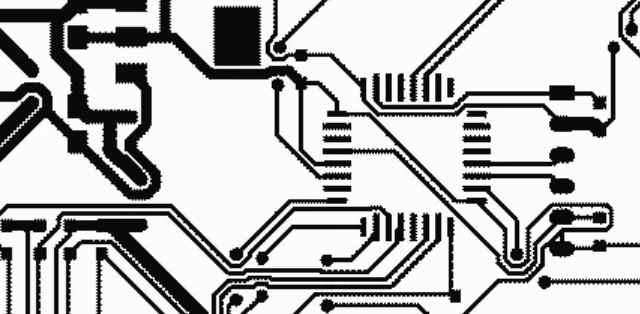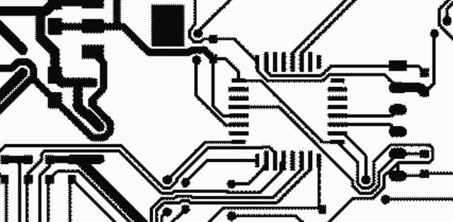
With copper plating protective agent plating copper layers in the air is not so easy to be oxidized, do not need to be extremely easy to oxidize, reason analysis is easy to be oxidized and lose luster, copper is soft and easy to activate, can form a good metal-metal bonding with other metal coating, so as to obtain a good bonding force between the coating. Therefore, copper can be used as the base of electrodeposition of many metals, and copper plating plays an important role in the production process of printed board. Copper plating on printed circuit board includes electroless copper plating and copper plating, among which copper plating is an important process in PCB manufacture. This paper mainly introduces the process technology of copper plating, the operation technical problems that should be paid attention to, the causes of some common faults and the treatment scheme.

The measures to eliminate this kind of failure are: according to the Hall tank test or to see the workpiece condition control plating solution brightener consumption ratio; Don't assume that the more brightener, the better the brightness. When the brightener is excessive, the low current density area will appear bright and not bright obvious boundary, complex parts coating flowers. When the more brightener is not bright, it is necessary to consider whether it is too much. At this time if a small amount of hydrogen peroxide treatment but the brightness increased, should be disposed of part of the brightener. For any plating additives, we must adhere to the principle of adding less and more often.
There are many brightener components (such as M, N type copper plating), it is necessary to accumulate appropriate brightener composition ratio in long-term production practice. The experience shows that the ratio of opening agent and supplement of bright copper plating is very strict, and the consumption of polydisulfide dipropanesulfonate is larger at different bath temperature, and the consumption ratio of M to N is also different. In order to obtain a general supplement ratio, only 25℃ ~ 30℃ ratio can be considered. The most ideal situation is to prepare a variety of brighteners into standard dilute solution, often with Hall tank test adjustment.
Control the content of chloride ions in the plating solution, if suspected failure is the cause of chloride ions in the plating solution, to confirm the first test, must not blindly add hydrochloric acid in the large tank adjustment control of copper sulfate and sulfuric acid content in the plating solution is also very important, and they are related to the anode dissolution and anode phosphorus content.
The accumulation of brightener decomposition products in the plating solution will result in poor brightening and levelling of the coating, and the low current density area is not bright. When it is found that with the same proportion of brightener in similar bath temperature conditions, the consumption is much higher than the normal value, it should be suspected that too much organic impurities. Organic solvent is too much, and there is no copper powder in the bath; However, copper powder precipitates with poor adhesion will be precipitated on the coating. Organic impurities in the bath should be treated at this time. In addition, do not ignore the adverse effect of organic impurities on the brightness of low current density area, the sensitivity of organic impurities is particularly strong when the current is small. It has been proved by practice that the full brightness range of low current density area of Hall groove test piece can be extended by several millimeters when organic impurities are absorbed by 39/L high-quality activated carbon alone for bright copper plating solution that has not been treated for a long time.
How do PCB boards solve crosstalk problems?
1. The conversion rate of the low signal along the possible landing condition
While meeting the design standards, try to choose slow devices, usually at the time of device selection. And to prevent the mixed use of signals of different varieties, because the fast changing signal has potential crosstalk risk to the slow changing signal.
2. Adopt shielding measures
It is an effective way to deal with crosstalk problem that the circuit board can provide the circuit board with a high speed signal. But. Making the already limited wiring area more congested. In addition, ground shielding to reach the expected destination line ground point spacing is very critical, generally less than two times the length of the signal along the change. At the same time, the ground wire will also increase the spread capacitance of the signal, so that the impedance of the transmission line is increased, and the signal along the slow.
3. Set the layer and wiring reasonably
The length of parallel signal should be reduced, and the wiring layer and spacing should be set reasonably. Crosstalk can be effectively reduced by shortening the distance between signal layer and plane layer, increasing the distance between signal lines and reducing the length of parallel signal lines (within the critical length range).
4. Set up different wiring layers
And set plane layer reasonably, set different wiring layer for different speed signal. It's also a good way to deal with crosstalk.
It can also greatly reduce the amplitude of crosstalk. If the impedance of the near or far end of the transmission line matches the impedance of the transmission line.


