
Professional PCB manufacturing and assembly
Building 6, Zone 3, Yuekang Road,Bao'an District, Shenzhen, China
+86-13410863085Mon.-Sat.08:00-20:00

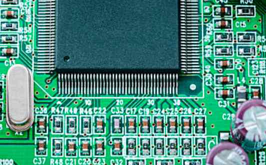
Any PCB board is the first thing to check, why?
Whether it is to let others do the board, or their own design and production of PCB board, the first thing is to check the integrity of the board, such as tin plating, cracks, short circuit, open circuit and drilling problems, if the role of the board is more rigorous, then you can check the resistance value between the power supply and ground.
Under normal circumstances, the DIY board will install the components after the completion of tinning, and let people do it, just a tin plated PCB board shell with holes, when you need to get the components.
Some people have more information about their designed PCB board, so they like to test all the components at once. In fact, it is better to do it bit by bit.
The debugging of the new PCB board can start from the power supply. The safest way to do this is to run a fuse and connect it to a power source (use a regulated power source just in case).
Use the regulated power supply to set the current protection, and then the regulated power supply voltage up slowly, this process needs to monitor the input current, input voltage and output voltage of the board.
When the voltage is raised in the process, there is no overcurrent protection and the output voltage is normal, then it means that the power supply part of the board is no problem, if it exceeds the normal output voltage or overcurrent protection, then it is necessary to check the cause of the fault.
Circuit board component installation
In the debugging process will gradually install the module, each one or a few modules, follow the above steps to test, which is conducive to avoid the design of some of the more secret errors, or installation components error, resulting in overcurrent burn components.

If a fault occurs during the installation, use the following methods to rectify the fault:
Troubleshooting Method 1: Voltage measurement method
When there is overcurrent protection, do not rush to remove components, first confirm the power pin voltage of each chip, to see whether it is in the normal range. Then the reference voltage and working voltage are detected in turn.
For example, when the silicon triode is switched on, the voltage of the BE junction will be about 0.7V, and the CE junction is generally 0.3V or less.
When the BE junction voltage is found to BE higher than 0.7V(excluding special triodes such as Darlington here), it is possible that the BE junction is open circuit. In turn, checking the voltage at each point can eliminate the fault.
Troubleshooting method 2: Signal injection method
The signal injection method is more troublesome than voltage measurement. When transmitting the signal source to the input end, we need to measure the waveform of each subsequent point in turn, and find the fault point from the waveform.
Of course, you can also use tweezers to detect the input end, which is to touch the input end with tweezers and observe the response of the input end. Generally, this method is used in the case of audio and video amplification circuit (note: hot floor circuit and high voltage circuit do not use this method, which is prone to electric shock accidents).
The method detects that the former level is normal and the latter level is responsive, then the fault is not at the latter level, but at the former level.
Troubleshooting Method 3: Others
PCB circuit board appearance test machine
The above two methods are relatively simple and direct, in addition, such as the often said look, smell, listen, touch, etc., which belongs to the need for some experienced engineers to detect the problem.
Generally, "look" is not to see the state of the testing instrument, but to see whether the appearance of the components is complete; "Smell" mainly refers to whether the smell of components is abnormal, such as burnt smell, electrolyte smell, etc. Generally, components will emit an unpleasant burnt smell when damaged.
And "listen" is mainly to listen to the working state of the board sound is normal; About "touch", it is not to touch whether the component is loose, but to feel whether the temperature of the component is normal by hand. For example, under the working state, the cold component is hot, while the hot component is extremely cold. In the process of touching do not directly use the hand to pinch, in case the temperature is too high will burn the hand.


Just upload Gerber files, BOM files and design files, and the KINGFORD team will provide a complete quotation within 24h.