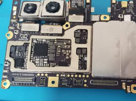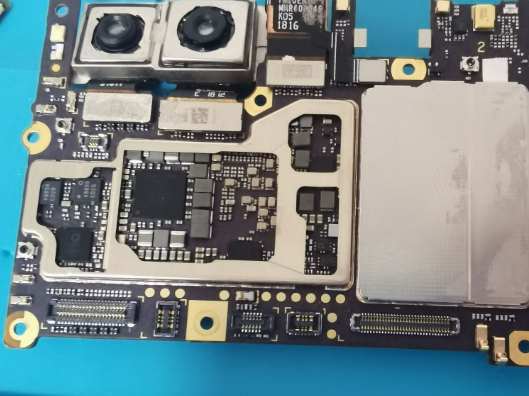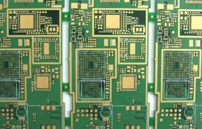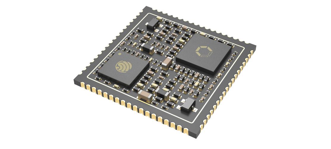
In general, in circuit maintenance, it is often required to assemble integrated circuit from PCB board. Because of the number and density of integrated circuit pins, it is difficult to assemble, and sometimes it will damage integrated circuit and PCB board. Here summarizes several effective integrated circuit assembly methods for your reference.
Multi-strandcopper wire tin absorption assembly method: is the application of multi-strand copper core plastic wire, remove plastic skin, the use of multi-strand copper core wire (can be applied to short wire). Before use, the rosin alcohol solution will be applied to multiple strands of copper core wire. After the electric soldering iron is heated, the multiple strands of copper core wire will be heated on the integrated block pin, so that the tin welding on the pin will be absorbed by the copper wire, and the local absorption of the solder can be cut off. Repeated implementation for several times can absorb all the solder on the pin. Braided wire in shielded wire can also be used if required. Simply suck up the solder, pry it quietly with tweezers or a small "one" flathead screwdriver, and the block can be removed.
Increasing solder ablation assembly method: This method is a convenient method. It only needs to add a little solder to the pins of the integrated block to be assembled, so as to connect the solder joints of each column of pins, so as to facilitate heat transfer and facilitate assembly. When assembling, each row of pins heated by electric iron should be pried with pointed tweezers or small "one" flathead screwdriver. The two rows of pins should be heated alternately until removed. Under normal conditions, each column of pins can be removed after heating twice.

Electric iron brush assembly method: This method is easy to do, as long as there is a electric iron and a small brush can be. When assembling the integrated block, the electric iron is heated first. When reaching the tin dissolving temperature, the solder on the pin is melted, and the melted solder is swept away with the brush. This allows the pin of the block to be separated from the printed board. The method may be applied separately or separately. Finally pry off the block with pointed tweezers or a small "one" flathead screwdriver.
Medical hollow needle assembly method: take medical 8 to 12 hollow needle several. It is appropriate for the inner meridian of the needle to cover the pin of the integrated block. During assembly, melt the pin solder with a soldering iron, cover the pin with a needle in time, then remove the soldering iron and rotate the needle, and pull out the needle after the solder condenses. The pin is then completely separated from the printed board. Once all the pins have been done, the block can be removed at will.
Pewter assembly method: The use of pewter assembly integrated block, this is a common professional method, the use of tools for ordinary pewter, welding dual-purpose electric iron, power above 35W. When assembling the integrated block, just place the heated dual-purpose electric soldering iron head on the pin of the integrated block to be assembled. After the solder spot is melted, it is sucked into the fine tin device. After the solder of all the pins is sucked, the integrated block can be removed.
Methods of dismantling integrated circuits
In circuit maintenance, it is often necessary to remove the integrated circuit from the printed circuit board. Because the pins of integrated circuit are many and dense, it is very difficult to disassemble, and it will damage the integrated circuit and printed circuit when disassembling is not good. The following describes several methods of disassembling integrated circuits.
1. Tin absorber tin suction disassembly method
Using a tin absorber to remove integrated circuit is a common professional method, the use of tools for suction, welding dual-purpose electric soldering iron. When disassembling integrated circuit, as long as the heated dual-purpose soldering iron head is placed on the solder joint of the pin of the disassembled integrated circuit, the solder joint will be sucked into the tin suction device after melting. After all the solder on the pins has been absorbed, the IC can be easily removed from the printed circuit board. The following method can be used when there is no tin absorber.
2. Special electric chromite head disassembly method
Figure 18-3 shows the shape of a dedicated electric soldering iron head. The special electric soldering iron head can be used to heat the pin solder joints of the integrated circuit at the same time. After the solder joints are melted, the integrated circuit can be gently removed from the printed board.
3. Hollow needle disassembly method
Commercially available hollow needles for disassembling electronic components can be used to disassemble integrated circuits. First of all, select a suitable hollow needle, with the inner diameter of the needle can just cover the integrated circuit pin as straight. When disassembling, melt the solder spot on the integrated circuit pin with an electric soldering iron, and rotate the pin with a hollow needle. Pull out the needle after the solder solidifies, so that the pin will be completely separated from the printed circuit board. Wait for each pin to press above
After the method is separated from the printed circuit board, the integrated circuit can be easily removed.
4. Electric soldering iron brush disassembly method
When disassembling the IC, the soldering spot on the IC pin is heated and melted with an electric iron, and the molten solder is swept away with a small brush, so that the pin of the IC can be separated from the printed circuit board. After all the pins are separated from the printed circuit board, the IC can be gently pry off with a "one" screwdriver. When using this method, attention should be paid to the solder under the sweep, do not make it connected to other parts of the printed circuit board. To prevent circuit short-circuiting.


