
Professional PCB manufacturing and assembly
Building 6, Zone 3, Yuekang Road,Bao'an District, Shenzhen, China
+86-13410863085Mon.-Sat.08:00-20:00

FPC Soldering Resistance Function and PCB Impedance Board Definition
PCB manufacturer, PCB designer and PCBA manufacturer explain FPC solder resistance function and PCB impedance board definition
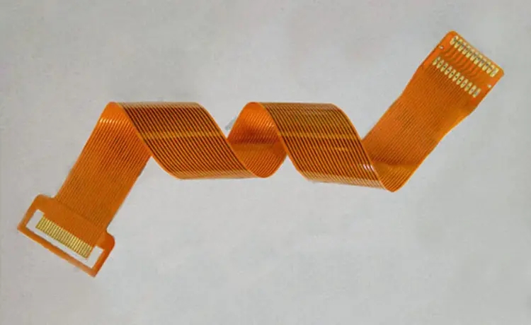
Green oil bridge, also known as solder bridge and solder dam, is a "isolation belt" made by the circuit board factory for bulk mounting to prevent short circuit of SMD component pins. To control the green oil bridge of FPC soft board (FPC flexible circuit board), it is necessary to control the solder resistance process. There are two kinds of FPC soft board solder resistance materials: ink and covering film.
Effect of Soldering Resistance on FPC FPC
1. Surface insulation;
2. Protect the line and prevent the line from being damaged;
3. Prevent conductive foreign matters from falling into the circuit and causing short circuit.
Ink used for solder mask is generally photosensitive, called liquid photosensitive ink. Generally, there are green, black, white, red, yellow, blue, etc. The covering film is generally yellow, black and white. Black has good light blocking property and high reflectivity of white, which can replace white oil black for backlight FPC soft board (FPC flexible circuit board). FPC soft board (FPC flexible circuit board) can be solder blocked with either ink or covering film.
Understand the definition and four elements of PCB impedance board
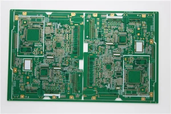
The definition of PCB impedance board is that a good laminated structure can control the characteristic impedance of PCB, and its routing can form a controllable and predictable transmission line structure called impedance board. Now we know what PCB impedance board is. Do you know some elements about PCB impedance board?
1、 Characteristic impedance control of printed circuit board
The characteristic impedance of the wire on the PCB is an important indicator of circuit design, especially in the PCB design of high-frequency circuit, whether the characteristic impedance of the wire is consistent with the characteristic impedance required by the device or signal and whether it matches must be considered.
2、 Impedance characteristics of printed circuit board
According to the signal transmission theory, the signal is a function of time and distance variables, so each part of the signal on the line may change. Therefore, the AC impedance of the line, that is, the ratio of the voltage change to the current change, is determined as the characteristic impedance of the transmission line: the characteristic impedance of the transmission line is only related to the characteristics of the signal line itself. In the actual circuit, the resistance value of the wire itself is less than the distributed impedance of the system, especially in the high-frequency circuit, the impedance of the characteristic PCB impedance board mainly depends on the distributed impedance brought by the unit distributed capacitance and unit distributed inductance of the connecting line. The characteristic impedance of an ideal transmission line only depends on the unit distributed capacitance and unit distributed inductance of the line.
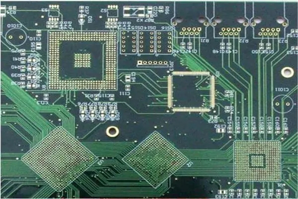
3、 PCB impedance control
There will be various signals transmitted in the conductor of the circuit board. When it is necessary to increase its frequency to improve its transmission rate, if the circuit itself is different due to etching, stack thickness, wire width and other factors, the impedance value will change and the signal will be distorted. Therefore, the impedance value of the conductor on the high-speed circuit board should be controlled within a certain range, which is called "impedance control". The main factors affecting the impedance of PCB wiring are the width of copper wire, the thickness of copper wire, the dielectric constant of the medium, the thickness of the medium, the thickness of the pad, the path of the ground wire, the wiring around the wiring, etc. Therefore, when designing PCB, we must control the impedance of the wiring on the circuit board to avoid signal reflection, other electromagnetic interference and signal integrity problems as much as possible, and ensure the stability of the actual use of PCB. The calculation method of microstrip line and stripline impedance on PCB can refer to the corresponding empirical formula.
4、 Impedance matching of printed circuit board
In PCB, if there is signal transmission, it is hoped that it can be smoothly transmitted to the receiving end from the sending end of the power supply with the minimum energy loss, and the receiving end will fully absorb it without any reflection. To achieve this kind of transmission, the impedance in the line must be equal to the impedance inside the transmitter to be called "impedance matching". When designing high-speed PCB circuits, impedance matching is one of the elements of design. The impedance value is absolutely related to the wiring mode. For example, whether to walk on the surface layer or the inner layer, the distance from the reference power layer or the stratum, the route width, PCB material, etc. will affect the characteristic impedance value of the route. In other words, the impedance value can only be determined after wiring, and the characteristic impedance produced by different PCB manufacturers also has slight differences. General simulation software can't take into account some discontinuous impedance wiring due to the limitation of line model or mathematical algorithm used. At this time, only some terminals, such as series resistance, can be reserved on the schematic diagram to mitigate the effect of discontinuous impedance. The real fundamental solution to the problem is to avoid impedance discontinuity when wiring.
PCB manufacturers, PCB designers and PCBA manufacturers will explain FPC solder resistance and the definition of PCB impedance board.


Just upload Gerber files, BOM files and design files, and the KINGFORD team will provide a complete quotation within 24h.