
Professional PCB manufacturing and assembly
Building 6, Zone 3, Yuekang Road,Bao'an District, Shenzhen, China
+86-13410863085Mon.-Sat.08:00-20:00

The names of circuit boards include: ceramic circuit board, alumina ceramic circuit board, aluminum nitride ceramic circuit board, circuit board, PCB board, a circuit boardsluminum substrate, high-frequency board, thick copper board, impedance board, ultra-thin circuit board, ultra-thin circuit board, printing (copper etching technology), etc. The circuit board makes the circuit miniature and intuitive, which plays an important role in the mass production of fixed circuits and the optimization of the layout of electrical appliances. The circuit board can be called a printed circuit board or a printed circuit board, and its English name is (Printed Circuit Board) PCB (Flexible Printed Circuit board) FPC PCB The birth and development of FPC and PCB (reechas, Soft and hard combined plate) has accelerated the birth of this new product. Therefore, the soft and hard combination board is a circuit board with FPC characteristics and PCB characteristics formed by combining the flexible circuit board and the hard circuit board according to relevant process requirements after pressing and other processes.
According to the number of layers, the road boards are divided into single panel, double panel and three major categories. First is the single panel. On the most basic PCB, parts are concentrated on one side and wires are concentrated on the other side. Because wires only appear on one side, this PCB is called single-sided circuit board. Single panel is usually simple to make and low in cost, but its disadvantage is that it cannot be applied to too complex products.
Double panel is an extension of single panel. When single-layer wiring cannot meet the needs of electronic products, double-sided panel will be used. Both sides are copper coated and wired, and the line between the two layers can be conducted through the via to form the required network connection.
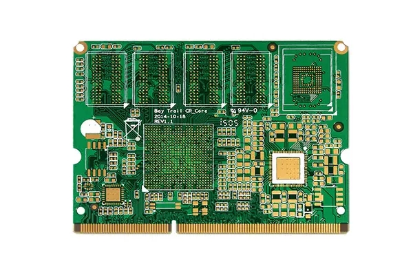
Multilayer board refers to a printed board with more than three conductive graphic layers and insulating materials between them laminated at intervals, and the conductive graphics between them are interconnected as required. Multilayer circuit board (MLPCB) is the product of the development of electronic information technology in the direction of high speed, multi-function, large capacity, small volume, thin and lightweight.
PCB can be divided into soft board (FPC), hard board (PCB) and soft hard combination board (FPCB) according to characteristics.
Generally, a complete machine is composed of several printed circuit boards, which can be large or small. The circuit contained in each printed board is often drawn on a circuit diagram. As a result, a complete machine circuit diagram is often composed of several block circuit diagrams. After understanding each block circuit diagram, you can understand the complete machine circuit diagram. Each block circuit diagram includes one or several circuit systems. The complexity of large block circuit diagrams is almost the same as that of ordinary small and medium-sized screen televisions. Although the circuit is relatively complex, and various block circuits perform different functions, they have rules to follow and can be read in a certain way.
In order to avoid detours when reading circuit diagrams, correct reading methods and steps should be used. The method of outflanking from the outside to the inside is usually adopted. The method of combining inside and outside, linking back and forth, and breaking through step by step can be used to read all circuit diagrams smoothly. The specific methods and steps of looking at the picture can be summarized into three sentences and three steps: start with the periphery and select the entrance; Open the gap and contact the front and rear; The difficulty analysis shall be put at the end.
Circuit board
1. Start intuitively and choose the entrance
In other words, first look at the most intuitive and easy to read components and circuits at the edge of the circuit as the entrance to read the diagram. A batch of circuits or integrated blocks can be found along the signal line inwards (possibly in the opposite direction to the signal flow direction) by these peripheral read-out parts.
Open the gap and contact before and after
There are some weak points in any circuit diagram. The complexity and ease of each part of the circuit are always different, or the graphics and symbols of some components are different from those of general components. These places are the internal weak links and easy to read links of drawing reading. They can be used as the internal breakthrough of drawing reading. These places can be selected as the breakthrough points for map reading. After opening the gap, you can quickly connect forward, backward, left and right, and cooperate with the first step method to read many circuits.
As long as readers pay attention, there will always be many links that readers are already familiar with inside the circuit diagram. Grasping it can quickly open the gap in viewing the diagram and develop in depth. The most intuitive and easy to read internal link is the integrated circuit, especially those large-scale integrated circuits, which have more than 40 lead pins and more than 100 lead pins, which are very eye-catching in the figure
Always place them in the center or obvious position of the circuit diagram. Then, with these integrated circuits as the center, we can find
Many circuits. There is a prerequisite for using integrated circuits as internal breakthrough. You must know the specific models of these integrated circuits, know the main functions of this model of integrated circuits, and be familiar with the names and purposes of their main pins. Otherwise, it will bring a lot of inconvenience to reading drawings. Sometimes the reader is familiar with most integrated circuits, but not with some individual integrated circuits. According to the block diagram and the context, the function of the unknown integrated circuit can also be guessed.
There are also some easy to read and remember contents in the circuit diagram, which can also be used as a breakthrough inside the circuit. For example, Chinese characters, foreign letters or abbreviations marked in the drawing, some important and readable component graphical symbols, some adjustable resistors or potentiometers, etc. In order to use these breakthroughs conveniently and smoothly, readers should be familiar with the physical meanings of various foreign letters and abbreviations, have a certain foreign language foundation (generally English), and be familiar with some professional terms and abbreviations frequently used in audio-visual equipment; Readers should be familiar with the functions, parameters and indicators of these components. Readers should have a wider range of knowledge, which is conducive to reading pictures. Readers should consciously remember some useful common sense.
3. Difficulties analysis, put last
After the above two steps of reading, most of the contents of the circuit diagram can be understood. However, there are still some local circuits that have not been understood or not understood. The third step can be used exclusively for encirclement and annihilation difficulties. This is the difficult part and the last step of looking at the picture. Readers can break through difficult circuits by various methods or means.
On the practical circuit diagram, there are two places that are difficult to understand. One is the signal flow processing process inside some integrated circuits. Because these contents are not understood, the function of its external lead out pin cannot be understood; The other is some peripheral discrete component circuits, which do not understand the purpose of setting the circuit and the signal processing process. For these difficult circuits, we can always understand these difficult circuits according to the block diagram of the whole machine, the functions and interrelationships of each part of the circuit, and through logical analysis, functional and signal flow analysis methods.
In fact, there is a lot of information available for reading and using on the circuit diagram. With the readers' synthesis, analysis and research, you will be able to understand the whole diagram. Each person's actual situation is different, the methods of looking at the picture and judging may be slightly different, and the steps of looking at the picture are not unchanging. With the rapid development of electronic technology, manufacturers often develop new circuits or circuits with new functions, and even circuit programs are quite strange. Based on the above basic idea of looking at pictures, you can flexibly complete the work of looking at pictures.
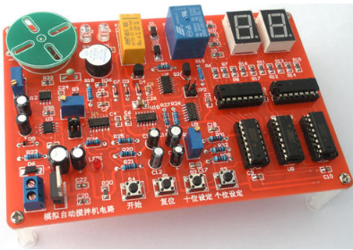
For beginners of electronic technology, mastering basic circuit principles, functional characteristics and detection of components, how to analyze schematic diagrams, look at PCB, welding technology of components and common maintenance methods are all basic skills that need to be mastered. Here's how to look at PCB. I hope it will be helpful to beginners.
PCB is the printed circuit board. The component layout on PCB is quite different from the schematic diagram, which will make beginners feel "complicated" and difficult to see those lines. It doesn't matter. After you read the following PCB analysis tips, you can do some exercises that must be correct.
There is a magic way to know PCB components
1. In the actual analysis of PCB, first of all, according to its shape, see what components this component looks like before. However, this accuracy is not high, so you have to look more often to see more widely.
2. Secondly, the identification is based on the printing of the components themselves. Generally speaking, the printing represents some parameters or models, of course, there are also attributes such as the manufacturer's batch number and version number, and some even have symbols connected with some international certification. This method also depends on the usual understanding of the components' models and parameters.
For example, for a triode like device, C1815 is a low-power low-frequency NPN type triode; TL431 is an integrated voltage stabilizing IC; If 13001 is marked, it is a small power switch tube, which can be used in small small power charger.
Once again, you can disassemble the components to see the internal structure, which encourages you to try more, and more is better.
Components of a certain type or series have the same or similar structural characteristics. They are disassembled a lot and are more familiar with the internal structure and working principle of components. You can disassemble as many components as possible to further improve your basic component knowledge.
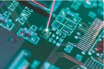
3. If the components are on the PCB, it can be judged according to the component symbols and silk screen on the PCB. If R12 is marked, it is the resistance, which is numbered 12 in the circuit. 10. Y and Z can both represent crystal oscillators. At the same time, you can judge the functions of components according to their circuits, and then analyze which components they belong to. This requires you to be familiar with the basic circuits.
Due to PCB technology, production and manufacturers, the same component will have different shapes, structures and materials, which will bring some difficulties when you analyze PCB. If conditions permit, you can go to special electronic component stores and electronic cities to learn more, which will help you accumulate knowledge.
Detailed explanation of PCB analysis skills
Make clear the components, general working principle, working process (especially the working process of DVD, washing machine, water heater, air conditioner, etc.), signal flow and the position of core components on PCB. To analyze an electrical appliance or electronic product, we should first understand it in general, and then analyze it in detail by subdividing circuits and components.


Just upload Gerber files, BOM files and design files, and the KINGFORD team will provide a complete quotation within 24h.