
Professional PCB manufacturing and assembly
Building 6, Zone 3, Yuekang Road,Bao'an District, Shenzhen, China
+86-13410863085Mon.-Sat.08:00-20:00

Detailed explanation of connector connection mode of PCB
PCB manufacturers, PCB designers and PCBA manufacturers explain the connection methods of PCB connectors in detail
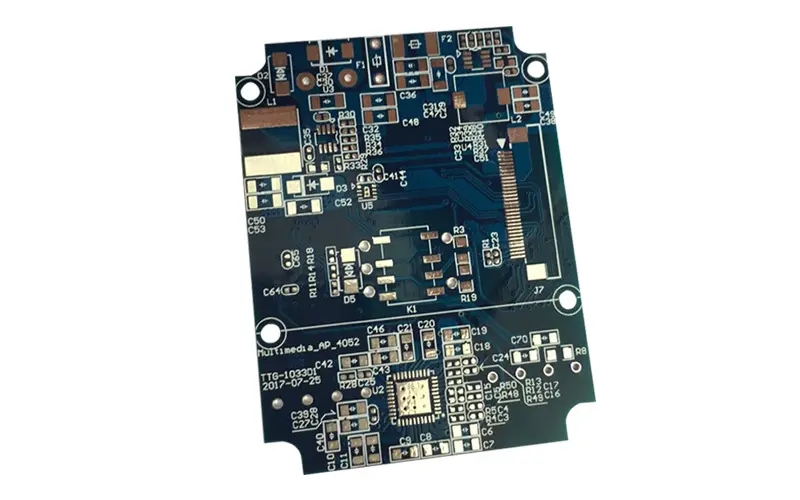
As a component of the whole machine, a PCB cannot generally constitute an electronic product, and there must be a problem of external connection. For example, electrical connection is required between PCBs, between PCBs and components outside the board, and between PCBs and equipment panels. It is one of the important contents of PCB design to select the connection with the best combination of reliability, technology and economy. Today, we will discuss the connector connection mode of PCB.
In more complex instruments and equipment, connector connection is often used. This "building block" structure not only ensures the quality of mass production, reduces the cost of the system, but also provides convenience for debugging and maintenance. When the equipment fails, the maintenance personnel do not need to check the component level (that is, check the cause of the failure and trace it back to the specific component. This work takes a lot of time), as long as they judge which board is abnormal, they can immediately replace it, eliminate the failure in the shortest time, shorten the downtime, and improve the utilization of the equipment. The replaced circuit board can be repaired in sufficient time and used as a spare part after repair.
1. Standard pin connection
This method can be used for external connection of PCB, especially pin connection is often used in small instruments. The two PCBs are connected through standard pins, and they are generally parallel or vertical, which is easy to achieve mass production.
2. PCB socket
This method is to make a printed plug from the edge of the PCB. The plug part is designed according to the size of the socket, the number of connection points, the contact distance, the location of the positioning hole, etc., to make it match the special PCB socket.
During plate making, the plug part needs to be gold-plated to improve wear resistance and reduce contact resistance. This method is simple in assembly, good in interchangeability and maintenance performance, and suitable for standardized mass production. Its disadvantage is that the cost of PCB is increased, and the requirements for PCB manufacturing precision and process are high; The reliability is slightly poor, and the contact is often poor due to the oxidation of the plug part or the aging of the socket spring. In order to improve the reliability of external connection, the same outgoing line is often led out in parallel through the contacts on the same side or both sides of the circuit board.
PCB socket connection mode is commonly used for products with multi board structure. There are two types of sockets: reed type and pin type.
PCB manufacturers, PCB designers and PCBA manufacturers will explain the connection methods of PCB connectors in detail.


Just upload Gerber files, BOM files and design files, and the KINGFORD team will provide a complete quotation within 24h.