
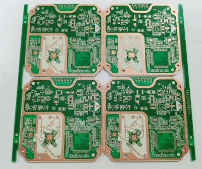
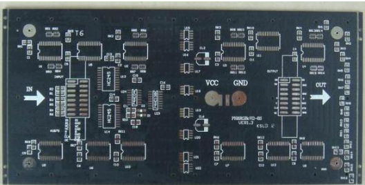
Professional PCB manufacturing and assembly
Building 6, Zone 3, Yuekang Road,Bao'an District, Shenzhen, China
+86-13410863085Mon.-Sat.08:00-20:00

The microminiaturization, intelligence and intelligent system regulations of the new generation of portable electronic devices have promoted the use of high-density assembly PCB and high-density interconnection (HDI) multilayer circuit boards to become increasingly common. The traditional laminated pcb manufacturing process can no longer be integrated into the application of ultra-fine particle spacer components. HDI board refers to a PCB whose graphic limit/line spacing is not more than 0.11mm and micro conduction diameter is not more than 0.15mm.
This commodity stipulates that the substrate material has high temperature resistance, excellent mechanical equipment performance, low thermal conductivity, low linear expansion coefficient and other provisions, and their stacked layer structure and manufacturing process are more and more complex.
Characteristics and regulations of basic materials for high-density PCB assembly
The high-performance organic chemical forced PCB substrate is generally composed of a dielectric layer (epoxy resin adhesive, glass fiber) and a high-purity electrical conductor (copper foil). The key parameters for evaluating the quality of printed pcb circuit board substrate include glass transition temperature Tg, linear expansion coefficient CTE, high temperature resistant dissolution time and temperature Td of substrate, electrical equipment performance, water absorption of PCB, electromigration CAF, etc.
The PCB substrate is a part of the insulating layer composed of glass fiber, non-woven materials and its epoxy resin, and then is restrained into "adhesive sheets" by epoxy resin glue and copper foil. The board's own substrate is made of insulating layer materials that are not easy to bend. It is widely used on the high-density interconnection multilayer circuit board of the new generation of high-precision electronic devices. They are more and more strict in terms of the thermal performance, mechanical equipment performance, and environmental protection regulations of the substrate, and the structure and manufacturing process of the stacked layers have become complex. However, the specification reliability, tensile strength, rigidity, ductility, etc. of PCB are limited by the characteristics of substrate material. Professional and technical personnel should make comprehensive consideration on the design scheme or process according to the commodity characteristics, high cost performance ratio of material, high efficiency and reliability of panel assembly.
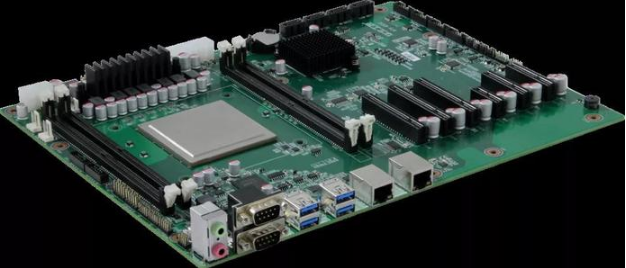
High precision circuit board
Miniaturized HDI products refer to the reduction of product specifications and net weight, such as wireless Bluetooth earphones, smart phones and portable smart home products. These products are completed according to the design scheme of improving the relative density of cabling, using small and medium-sized electronic devices such as CSPFC, internal interconnection of 6-layer or 8-layer boards, and according to the selection of buried hole technology. The thickness of most of these substrates is less than mm, and they are FR4 materials with high Tg (160 ℃).
HDI boards of high-density substrate are generally above 4 layers. Virtual beams are interconnected by embedded holes or embedded holes. At least 2 layers of them have microporous plates, which are applicable to FC or bonded substrates. The microporous plate process provides sufficient spacing for high-density flip chip integrated circuits. Microwell boards are designed to handle PCB high-density routing. According to the fact that today's micro well boards have been changed from CNC to laser drill, some CSP metallized holes are even less than 100 μ m. Microwell plate process can produce high I/O component spacing.
The number of HDI boards for high-rise residential buildings generally refers to the traditional pcb multilayer boards with laser drilling from the first to the second or the third layers. The sequential stacking process is selected to carry out microporous processing on the raw materials of laminated glass. The technical purpose is to embed sufficient indoor space for components to ensure the specified characteristic impedance level, and to apply to the number of boards in high-rise residential buildings with high I/O numbers or fine spacing components.
In the traditional pcb multilayer board process, all layers are stacked into a PCB at one time, and the whole line through buried holes are selected to carry out virtual beam edge connection. In the HDI board process, the electrical conductor layer and cable sheath are stacked step by step, and the connection between electrical conductors is based on micro buried or blind holes. With the increase of the relative density of PCB substrate interconnects, full integrated layer or random layer interconnects have just been applied. Therefore, HDI board process is generally called BUP or BUM. According to the way of micro buried or blind hole on/off, it can be further subdivided into electroplating process hole deposit and conductive deposit.
Among HDI board processes, electroplating process hole process is a popular one, which basically accounts for more than 95% of HDI board sales market. It is also in a continuous development trend. From the initial traditional hole electroplating process to the hole filling electroplating process, the playability of HDI board design has been greatly improved. For the design scheme of multilayer plate with electroplating process holes, the key consideration is the number of layers stacked, the structure of buried holes and micro blind holes, and the specification of micro blind holes. In addition, there is also the technical ALIVH process of random layer gap filling on/off interconnection, which is based on the conductive adhesive hole filling to complete the random virtual beam interconnection of the layers, all completed by burying blind guide holes. Its main characteristics are: first, non-woven aramid fluorobenzene chemical fiber epoxy resin adhesive semi dry solid sheet is used as the base material; second, carbon dioxide laser is used to generate buried holes and conductive paste is used to fill the buried holes, or conductive paste is used to make bumps.
There are two kinds of common base materials: polyester, commonly known as PET, which is superior in quality and low in price. The electrical equipment and physical properties are similar to those of polyurethane and can be well resistant to humidity and cold. Its thickness is 1~5mil. PET is applicable to the office environment of - 40 ℃~55 ℃, but its heat resistance is weak, so it is only applicable to simple FPC and cannot be used on FPC boards with components. Polyammonia is commonly known as PI. It has excellent heat resistance, and its resistance to immersion welding reaches 260 ℃/20s. It is basically used in all national defense hardware configurations and strictly regulated commercial machinery and equipment. PI material is easy to get damp and expensive, and its thickness is generally 0.5-5CIL.
In a word, FPC or Rigid FPC substrates include injection moulded copper (RA) and electrolytic nickel (ED). Injection moulded copper is generally used for dynamic products with high bending frequency, while electrolytic nickel is only used for static data products with low bending frequency. Common insulating layer materials include polyurethane (PI) and polyester (PET). PI is expensive and has good heat resistance. The resistance to immersion welding reaches 260 ℃ for 20s. However, these materials are prone to moisture. Before SMT production, they need to be baked to remove moisture; Although PET is cost-effective, it has poor heat resistance and is not suitable for SMT flow back welding.
Thermal performance specification and selection of high-precision electronic device assembly board
In PCB material selection and design scheme, the mechanical equipment performance and thermal performance of the material should be suitable for the characteristics of the commodity, and the problems of plate warping and ground stress caused by back welding or wave welding process must be considered. The specification reliability, tensile strength, stiffness and reliability of PCB are greatly affected by the substrate material. If the material selection is not suitable, the PCB will be deformed before assembly, which will result in poor packaging and printing of high-precision fine spacing components. The reasonable layout and copper coating of PCB substrate must be uniform to balance the welding stress. For example, the copper dot of PCB copper clad plate is stronger than that of copper mesh.
The substrate materials of common pcb circuit boards can be divided into two categories: organic chemical substrate and inorganic substrate. The common organic chemical materials include paper based, epoxy resin glass cloth based, polymer based, and kneading base copper-clad polyimide film; the inorganic materials include ceramic substrate, metal material substrate, and copper-clad polyimide film fiberglass board for high-frequency circuits, and BT epoxy resin. For high-precision electronic circuit pcb board, they have strict regulations on the material, structure and thermal performance of the substrate.
The electronic optical packaging technology MPT is becoming more and more mature, especially in the application and promotion of hand-held portable products; The very small passive components of 0201 and 01005, and the ultra narrow gap components of micro gap technical MPT are more and more widely used. The steep increase in the relative density and processing speed of circuit board assembly, as well as the stringent environmental protection regulations for electronic equipment, not only are the regulations on substrate materials more and more stringent. When selecting materials for high-precision PCB design, we need to investigate the thermal properties of the substrate: glass transition temperature Tg, thermal expansion index CTE, high temperature resistance dissolution time and dissolution temperature Td. The substrate material Tg is the critical temperature for determining the performance of raw materials, and is an important main parameter for selecting the substrate raw materials. When the Tg is too low, the PCB is easy to expand and shrink, and the I/O welding end of the PCB is easy to cause the problem of coplanarity, and the ground stress and welding stress of mechanical equipment damage the spot welding and electronic devices.
Based on your understanding of the structure, thermal performance and electrical equipment performance of high-precision electronic circuit pcb boards, such as the material and structural characteristics of high-density assembly boards, glass transition temperature Tg, linear expansion coefficient CTE, PCB dissolution temperature Td, high temperature resistance dissolution time, thermal conductivity, dielectric loss, electrical resistance and compressive strength, grounding resistance, electrical insulation resistance, PCB water absorption, electromobility CAF, etc, So that when we do pcb design and substrate selection, we can be more confident and appropriate.


Just upload Gerber files, BOM files and design files, and the KINGFORD team will provide a complete quotation within 24h.