
Professional PCB manufacturing and assembly
Building 6, Zone 3, Yuekang Road,Bao'an District, Shenzhen, China
+86-13410863085Mon.-Sat.08:00-20:00

7 considerations for sharing PCB power supply design
Have you considered how to transmit power in a complex PCB? Yes, for PCB designers, designing a power supply to provide the required power for each PCB component (IC, transmitter, capacitor, etc.) is a difficult task, because the power requirements for each component are different. Only a perfect power supply design can help overcome this challenge.
With the increase of circuit design density and complexity, the complexity of power supply design has been amplified. Several possibilities of PCB power supply design and layout are provided for PCB designers. Although PCB power supply designs are diverse, designers must follow certain rules and deal with common problems related to them.
Some common issues to be addressed in power supply design include EMI, routing design for handling high currents, reducing current loops, selecting components, and following layout recommendations in data sheets.
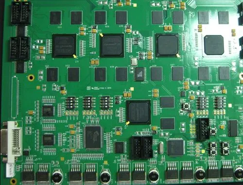
PCB power supply design
Precautions for PCB power supply design
Select appropriate PCB power regulator
Thermal management of power supply
Ground plane and power supply layer can provide better PCB power supply
Decoupling capacitor and bypass capacitor
EMI filtering
Frequency response of transmission system
Power integrity (PI)
PCB power supply design
The purpose of power supply design is not only to convert the power supply from AC to DC. The function of the power supply is to supply power to the circuit components at the correct voltage and current. In the future, the voltage is usually as low as 1.8V and 1.2V devices. Low voltage will reduce the tolerance of power supply noise.
The power supply also requires a current limit to limit the maximum current. Therefore, the important parameters of power supply are voltage, maximum current, voltage ripple and heat loss under maximum current.
Precautions for PCB power supply design
When designing power supply, the importance of PCB with reasonable layout cannot be overemphasized. In addition, designers must understand the importance of power operation to make this work successful.
For power supply design, designers need to execute good PCB layout and plan effective distribution network. In addition, designers need to ensure that noisy digital circuit power is separated from critical analog circuit power and circuits. Here are some important things to consider:
1. Select appropriate PCB power regulator
Generally, designers have two choices when choosing power supply regulators, namely, linear regulators and switching mode regulators. The linear regulator provides a low noise output, but has a high heat dissipation, so a cooling system is required. Switching mode regulators are efficient over a wide current range, but switching noise can cause spikes.
A linear mode requires a higher input voltage than the required output voltage, because there will be a minimum voltage difference. The linear regulator will have considerable power loss and heat dissipation, which will reduce the efficiency of the linear regulator. If you are considering using a linear regulator for PCB design, you must consider the regulator with low dropout and perform a thermal analysis before manufacturing. In addition, linear mode regulators are simple, inexpensive, and provide exceptional noise free voltage output.
The switch regulator temporarily stores energy in the inductor, and then releases the energy at different voltages at different switching times and converts one voltage into another. In this power supply, fast switching MOSFETs are used. The output of these high efficiency regulators can be adjusted by changing the duty cycle of the Pulse Width Modulation (PWM). The efficiency depends on the heat dissipation of the circuit, in which case the efficiency is very low.
PWM switching of switching regulators can cause noise or ripple in the output. Switching current can cause noise crosstalk in other signals. Therefore, the switching power supply needs to be isolated from key signals.
Switching regulators use MOSFET technology, so it is clear that these regulators emit EMI (electromagnetic interference) noise. We cannot completely eliminate EMI in any circuit, but we can minimize it through measures to reduce EMI (such as filtering, reducing current loops, ground planes, and shielding). Electromagnetic compatibility (EMC) measures should be considered before adding switch mode regulators to your design.
Linear and switching regulated power supply are two obvious choices when selecting voltage regulator. Linear control power is cheaper, but inefficient, and emits more heat. At the same time, switching regulated power supply is expensive and needs to connect more passive components, so it is not easy to heat up.
2. Thermal management of power supply
The performance of the power supply directly depends on the cooling. Most electronic components generate heat whenever an electric current passes through them. The heat emitted depends on the power level, characteristics and impedance of the component. As previously mentioned, selecting a suitable voltage regulator can reduce the heat dissipation in the circuit. The heat dissipation of switching regulator is small, so it is very efficient.
Electronic circuits work more effectively at lower temperatures. To ensure that the device works at ambient temperature, the designer should consider appropriate cooling methods.
If the linear regulator is selected by the designer, radiator or other cooling methods are recommended if the system allows. The fan can be integrated into the design to ensure forced cooling when the equipment has high heat dissipation.
The heat dissipation of the entire PCB may be uneven. Components with high power ratings can radiate a lot of heat, creating hot spots around them. Heat sink holes can be used near these components to quickly transfer heat away from the area.
The combination of cooling technology and cooling method can create efficient power supply design. Designers can use either conductive cooling methods (such as radiator, heat pipe, heat sink) or convection cooling methods (such as cooling fan, thermoelectric cooler, etc.).
3. Ground plane and power supply layer to provide better PCB power supply
The ground plane and power layer are low impedance paths for power transmission. The power supply requires a separate ground plane to distribute power, reduce EMI, minimize crosstalk, and reduce voltage drop. The power plane is dedicated to transferring power to the desired area of the PCB.
PCB designers need to deal with each part of the grounding network separately. In multilayer PCB, one or more layers can be specially used for ground plane and power supply layer. Moreover, they can reduce interference and crosstalk by placing a ground plane between the two active signal layers, thus effectively connecting the signal routing to the ground.
4. Decoupling capacitor and bypass capacitor
Power flow in general power supply design
When power is distributed to components on the whole board, different active components will cause ground bounce and ringing in the power rail. This may cause a voltage drop near the power supply pins of the component. In this case, the designer uses decoupling capacitors and bypass capacitors near the power supply pins of the components to provide short-term spikes in device current demand.
The concept behind decoupling is to reduce the impedance between the power supply and the ground. The decoupling capacitor of serves as the secondary power supply to provide the current required by the IC. It also acts as a local charge source to support switching events.
Bypass capacitors bypass noise and reduce fluctuations in the power bus. They are placed close to the device or IC and connected between the power supply and the ground to compensate for changes in the power supply and ground plane potential when many ICs are switched at the same time.
The bypass capacitor is used to suppress inter system or intra system noise in the power grid. All decoupling capacitors must be connected close to the power supply pin of the IC, with the other end directly connected to the low impedance ground plane. In order to minimize the series inductance of this connection, it is necessary to short-circuit the decoupling capacitor and the grounding through hole.
When selecting a local bypass capacitor, several aspects need to be considered. These factors include selecting the correct capacitor value, dielectric material, geometry, and capacitor position relative to the IC. Typical value of decoupling capacitor is 0.1 μ F Ceramics.
5. EMI filtering
EMI radiation may come from any power cord entering or leaving the power enclosure. PCB designers expect power supplies to keep their EMI below their defined spectral limits. Therefore, an EMI filter is used at the power input point to reduce conducted noise.
7 Tips and PCB Design Guidelines for EMI and EMC
The architecture of the EMI filter enables it to block high-frequency noise. It is essential that the designer carefully arrange the filter circuit components to prevent the components from transferring energy to the wiring connecting them
6. Frequency response of transmission system
When the power supply is suddenly loaded, such as from no load to full load, the voltage output will tend to drop briefly and return to normal voltage. In some cases, the output will oscillate for some time before the voltage stabilizes to a normal level. If the oscillation exceeds the design limit, the output capacitor and compensation capacitor must be adjusted. For example, for LM7805, it is recommended to place a 0.1 beside the output pin μ F Capacitor. Similarly, sudden unloading of the regulator may cause overshoot and oscillation.
In order to get better response from the circuit design, please ensure that the selected components are within the design constraints. Whether the circuit is AC or DC, their responses are different. AC and DC circuits shall be considered separately.
7. Power integrity (PI)
The designer shall ensure the power integrity of the power supply design. Power integrity is just the quality of power delivered to the circuit. This is a measure of the transmission efficiency of power from the system to the load in the system. It ensures that all circuits and equipment are provided with appropriate power to achieve the required circuit performance.
Less noisy power supplies ensure higher power integrity. Power integrity design is nothing more than managing power noise. There are some simulation tools that can help to estimate the power quality in the circuit. Such tools can help to estimate the voltage drop, it is recommended to use decoupling capacitors, and can also identify hot spots of high current in the circuit.
Good power supply is the key to the accurate operation of electronic equipment. As we can see, PCB designers have many choices when considering power supply design. Among these considerations, the selection of voltage regulator, capacitor and EMI filter is very important. Similarly, thermal effect and load response should also be considered when designing the power supply system.
Also, follow the recommendations mentioned in the Power IC Data Sheet. The thickness of trace and placement of components play an important role in power supply design. Circuit board assembly and circuit board processing manufacturers explain 7 precautions for PCB power supply design shared by circuit board manufacturers.


Just upload Gerber files, BOM files and design files, and the KINGFORD team will provide a complete quotation within 24h.