
Professional PCB manufacturing and assembly
Building 6, Zone 3, Yuekang Road,Bao'an District, Shenzhen, China
+86-13410863085Mon.-Sat.08:00-20:00

The Function of PCB Routing Current Capacity in PCB Design
When PCB design is involved, the limitation of PCB wiring current capacity is very important. Although the IPC-2221 General Design Guide is a good starting point, the PCB wiring width calculator provides accurate values that can be used for circuit board design.
The current capacity of the wiring on the PCB is determined by such parameters as the wiring width, wiring thickness, the required maximum temperature rise, whether the wiring is in the inner layer or the outer layer, and whether it is covered by solder resist.
In this article, we will discuss:
PCB wiring width
Current carrying capacity of PCB wiring
High current PCB
High current PCB layout guidelines
Design Skills of High Current PCB
PCB wiring width calculator
What is PCB wiring width?
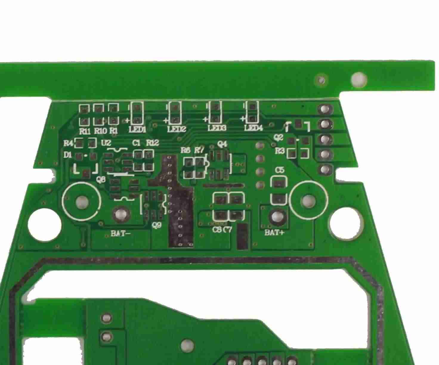
PCB wiring or PCB wiring is a copper conductor on the PCB board, which can conduct signals on the PCB surface. What remains after etching is the flat narrow part of the copper foil. The current flowing through the copper trace will generate a lot of heat. Correctly calibrated PCB routing width and thickness help minimize heat buildup on the circuit board. The wider the trace, the lower the impedance to the current and the less the heat accumulation. As shown in the figure below, PCB routing width is the horizontal dimension of routing, while thickness is the vertical dimension of routing.
PCB wiring structure
PCB development always starts from the default wiring width. However, this default routing width is not always suitable for the required PCB. This is because you need to determine the routing width by considering the current carrying capacity of the routing.
When determining the correct routing width, there are several factors to consider:
Copper Layer Thickness – The copper thickness is the actual wiring thickness on the PCB. The default copper thickness for high current PCB is about 1 oz (35 microns) to 2 oz (70 microns)
Cross sectional area of wires – Higher power requirements on PCB require larger cross sectional area of wires. This is proportional to the wire width.
Location of trace – bottom layer or top layer or inner layer
How do you design high current PCB?
Digital, RF and power circuits mainly process or transmit low-power signals. The copper weight for these applications is 1-2oz and the current carrying current is mA to 1A or 2A. In some applications, such as motor control, a current of up to 50A is required, which will require greater copper weight and wiring width on the PCB.
The conventional design method for high current demand is to widen the copper wire and increase the thickness of the wire to 2oz. This will increase the space requirements on the board and the number of layers on the board.
High current PCB layout guidelines
These are the guidelines for designing and manufacturing high current PCBs:
Keep high current wiring short
A longer cable has a higher resistance value and also carries a higher current, resulting in a higher power loss. Due to the heat generated by power loss, the life of the circuit board will be shortened. Therefore, it is very important to keep the wiring carrying large current as short as possible.
Calculate the wiring width under appropriate temperature rise
The trace width is a function of variables such as resistance and the current flowing through it, as well as the allowable temperature rise. Normally, a temperature rise of 10 ° C is allowed when the ambient temperature is higher than 25 ° C. If the material and design of the plate allow, the temperature can even be increased by 20 ° C.
Isolate sensitive components from heat
Some electronic components, such as voltage reference, analog-to-digital converter and operational amplifier, are sensitive to temperature changes. When these components are heated, their signals may change.
It is known that the high current plate will generate heat, so the above components need to be thermally isolated from the hot spot to some extent. You can do this by making holes in the board and providing a heat sink.
Remove the solder mask
To increase the current capacity of the wiring, you can remove the solder mask, which exposes the copper below. You can then add additional solder to the wire, which increases the thickness of the wire and decreases the resistance. This will allow more current to flow through the wire without increasing the wire width or additional copper thickness.
Use polygon pouring at high current components
Field programmable gate array (FPGA) and processor are packaged with ball grid array (BGA) and line grid array (LGA), which require high current. To achieve high current flow, you can pour square polygons directly below the chip, then pull down the vias and connect them. You can then link polygon pours to thicker power runs or power planes.
Use internal layers for high current paths
If the outer layer of the PCB does not have enough space to place thicker routing, it can be filled in the inner layer. Next, you can use vias to link to high current devices that exist in the outer layer.
Add copper bars for very high current
For electric vehicles and high-power inverters with current exceeding 100A, copper wiring may not be the best method to transmit power and signals. In this case, you can use copper bus bars that can be soldered to PCB pads. The copper busbar is much thicker than the wiring, and can carry high current as required without any heating problem.
Use through hole stitching to conduct multiple wiring on the multi-layer bearing high current
When the routing cannot carry the required current in a single layer, the routing can be routed on multiple layers and handled by stitching the layers together. This will increase the current carrying capacity when the thickness of the two layers of wiring is the same.
What is PCB wiring width calculator?
Trace width depends on many factors, such as copper layer thickness, trace position length of trace, etc., so it is difficult to calculate accurate values manually. This is why most PCB manufacturers provide tools to calculate the routing width. The PCB wiring width calculator is a tool that takes all the above factors into account to provide an accurate value for the required wiring width.
According to IPC-2221 general standard for PCB design, PCB wiring current limit can be further divided into internal conductor and external conductor.
When determining the current capacity of the wiring, there are complex factors at play. However, PCB designers can rely on the reliability of the wire thickness calculator to help effectively design their circuit boards. When designing a reliable and high-performance PCB, it may take a long way to correctly set the routing width and its current carrying capacity. PCB assembly and PCB processing manufacturers explain the role of PCB routing current capacity in PCB design, PCB routing width, and PCB routing current carrying capacity.


Just upload Gerber files, BOM files and design files, and the KINGFORD team will provide a complete quotation within 24h.