
Professional PCB manufacturing and assembly
Building 6, Zone 3, Yuekang Road,Bao'an District, Shenzhen, China
+86-13410863085Mon.-Sat.08:00-20:00

Embedded Optical Interconnection in PCB for Ultra High Speed Design
5G will arrive earlier than you think, creating a lot of new opportunities for PCB designers, manufacturers and companies providing optical network equipment. The huge data transmission rate in 5G network, aerospace and other professional applications requires more use of optical interconnection in the entire electronic system, and ultimately needs to be converted to electro-optical systems and all photon systems. What can PCB designers do to keep up with this trend? The fact is that PCB designers may soon integrate optical interconnects into their standard boards.
Why Optical Interconnect?
Most PCB designers - except those engaged in optical transceivers - may not be aware of the upcoming silicon photonic integrated circuit (PIC), electronic photonic integrated circuit (EPIC) revolution and the greater development of embedded optical systems other than telecommunications. Applications other than telecommunications that require large data transmission rates (for example, military and aerospace systems) have used optical fiber for embedded computing.
In the telecommunications field, more electronic infrastructures will need to be replaced by equivalent optical infrastructures to achieve the faster and faster data transmission rate required by 5G networks. As electrical signals switch at a faster rate, signal integrity problems such as crosstalk and radiated EMI become more serious, and the loss on the standard substrate will increase at higher frequencies. Although the wireless transmission from the cellular tower to the user's mobile device is still wireless, the network and tower itself need to interface with the optical network to adapt to the large amount of data moved through the network.
Replacing the electrical infrastructure in PCB for network devices with optical interconnects can alleviate many signal integrity problems. Using multimode fiber, you can increase the number of channels in a single interconnect without increasing the cabling density. This allows expanding the data rate without significantly expanding the board size or component size.
If you think all this sounds like an episode from Star Trek, please rest assured that this technology is closer to commercialization than you think. Organizations like AIM Photonics are supporting the development of photonic microprocessors. Research groups and private companies are developing electronic photonic integrated circuits. Many people in the community have created proof of concept boards, including optical interconnects for connecting optical and electronic components
In some cases, more use of optical signals beside standard electronic devices will take up too much space, so that it is impractical to place cables in the chassis. Think about the space required to form 50 or more optical connections in a chassis with optical cables, and all of these will not exceed the minimum bending radius... It is impossible to meet the shape and performance requirements. This means that electronic manufacturers will need to print optical waveguides directly on PCBs.
Optical interconnection options for PCBs
The two best choices for optical interconnection in PCB are to embed glass fiber in the inner layer of multilayer PCB. Another option is to deposit polymer waveguides on the inner layer or the surface layer. Glass fibers can also be placed on the surface layer, but the geometry can be better controlled using polymers.
This becomes important for connecting optical elements, because geometric and coupling optical elements must be precisely defined at the surface layer. No matter which method is used, the design process will not change significantly, because optical interconnects will not encounter the same signal integrity problems as interconnects.
Glass optical interconnects are probably the easiest to integrate into standard multilayer PCB manufacturing processes because they can be embedded in core layers or prepreg layers. Suitable materials between FR4 laminates can be used as cladding layers of glass waveguides. There is no reason why glass or polymer cannot be used at the same time; The standard glass of the optical fiber can be used for the inner layer, while the polymer is easiest to deposit in the outer layer.
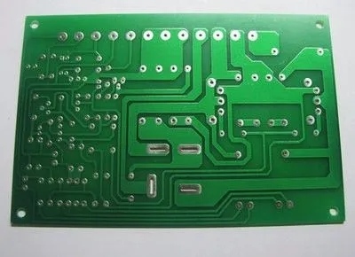
Circuit board with embedded glass optical interconnection.
Glass or polymer waveguides placed in the inner layer of PCB need to be transmitted back to the surface layer and coupled optical devices for EPIC/PIC, or use photodetectors with fast response time (usually PIN photodiodes). Especially in the optical BGA for EPICS and PIC, optical interconnection requires some type of coupling optics in the form of 45 degree mirrors. This requires extremely precise micro fabrication. Otherwise, the laser diode and receiver in the optical interconnection will need to be embedded in the substrate.
Looking forward to the future: manufacturing optical interconnection
The remaining challenges are mass manufacturing and more integration of optical elements and waveguides into PCBs for optoelectronic modules and backplanes. This requires scalable printing technology to directly fabricate dielectric waveguides on PCBs to connect various optical elements, electronic ICs, EPICs, and PICs. It is best to use polymers directly on FR4 PCB for optical interconnection, because they can be patterned using standard lithography technology.
As data rates become higher and higher, these optical interconnects will need to be scaled down to accommodate shorter wavelengths, although modal dispersion will become a continuous scaling problem, and as more modes are packaged into a given fiber. This does not mean that copper will be like dinosaurs; Copper is still necessary to isolate optical interconnects, especially in optical fiber radio applications. The research community and some companies have produced proof of concept boards with multimode waveguides, which operate at 12.5 Gbps and higher data rates.
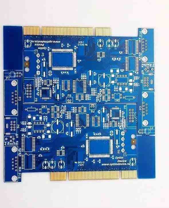
These fibers may appear in the core of multilayer PCB in the future
Anyone who is engaged in optical element work and wants to commercialize new products with optical interconnection can benefit from the full set of PCB design tools in Altium Designer. Industry standard layout and simulation tools are ideal for optoelectronic embedded computing and high-speed network applications. Data management and documentation tools can help you quickly prepare new designs for manufacturing.


Just upload Gerber files, BOM files and design files, and the KINGFORD team will provide a complete quotation within 24h.