
Professional PCB manufacturing and assembly
Building 6, Zone 3, Yuekang Road,Bao'an District, Shenzhen, China
+86-13410863085Mon.-Sat.08:00-20:00

Many PCB industrial control boards or RF boards will have a circle of vias and copper strips around the PCB board, and even some RF boards will have metallized edges around the board. What is the routine?
Design of Radiation Protection PCB for Multilayer PCB Board Edge
The edge radiation of multilayer PCB is a common electromagnetic radiation source
Nowadays, with the increase of system speed, not only the timing and signal integrity problems of high-speed digital signals are prominent, but also the EMC problems caused by the electromagnetic interference and power integrity of high-speed digital signals in the system are very prominent. The electromagnetic interference generated by high-speed digital signal will not only cause serious mutual interference within the system, reduce the anti-interference ability of the system, but also generate strong electromagnetic radiation in the outer space, causing the electromagnetic radiation emission of the system to seriously exceed the EMC standard, making the product unable to pass the EMC standard certification. The edge radiation of multilayer PCB is a common electromagnetic radiation source.
Edge radiation occurs when unexpected currents reach the edges of the ground plane and the power plane. These unexpected currents may originate from:
-Grounding and power supply noise caused by insufficient power bypass.
-The cylindrical radiation magnetic field generated by the inductive via radiates between layers of the circuit board and finally meets at the edge of the circuit board.
-The return current of the stripline carrying the high-frequency signal is too close to the edge of the circuit board.
Source of power noise
The source of power supply noise mainly lies in two aspects: one is that the transient alternating current is too large under the high-speed switching state of the device; The second is the inductance in the current loop. In terms of manifestation, it can be divided into three categories:
-Synchronous switching noise (SSN), sometimes referred to as Δ I Noise and ground bounce can also be classified into this category;
-Impedance influence of non ideal power supply;
-Resonance and edge effect.
In high-speed digital circuits, when the digital integrated circuit is powered on, its internal gate circuit output will undergo a state transition from high to low or from low to high, that is, the transition between "0" and "1". In the process of change, the transistors in the gate circuit will be continuously on and off. At this time, there will be current flowing from the connected power supply to the gate circuit, or from the gate circuit to the ground plane, so that the current on the power plane or ground plane will be unbalanced, resulting in a transient change of current △ I. When this current flows through the inductance on the return path, it will form an AC voltage drop, which will cause noise. If there are many output buffers for state transition at the same time, the voltage drop is large enough to cause power integrity problems. This noise is called Synchronous Switch Noise (SSN).
The AC noise of the power supply will be between the power supply layer and the stratum. The AC noise will be conducted by using the resonant cavity mode of these two planes, and will radiate into the free space when it reaches the edge of the plane, which will cause the product EMI to fail to pass the certification.
As for the noise generated by vias, we know that the interconnected signal lines on PCBs include the microstrip lines on the outer layer of the pcb, the stripline between two planes on the inner layer, and the electroplated vias (vias are subdivided into through holes, blind holes, and buried holes) that connect the signal layers. The microstrip lines on the surface layer and striplines between two planes can control radiation well through a good reference plane laminated structure design.
The vias run through multiple layers in the vertical direction. When the high-frequency signal transmission line passes through the vias for layer change, not only the impedance of the transmission line changes, but also the reference plane of the signal return path changes. When the signal frequency is relatively low, the effect of the vias on signal transmission can be ignored, but when the signal frequency rises to the RF or microwave frequency band, Because the change of the reference plane of the via causes the change of the current return path, the TEM wave generated by the via will propagate laterally between the resonators formed in the two planes, and eventually radiate outward into the free space through the edge of the pcb, causing the EMI index to exceed the standard.
OK, now we know that for high-frequency high-speed PCB, the edge radiation problem will occur at the PCB edge. How to protect it?
Protective Measures for Radiation at the Edge of Multilayer PCB
The three elements that cause EMC problems are: electromagnetic interference source, coupling path and sensitive equipment
Sensitive equipment is beyond our control. Cutting off the coupling path, such as adding a metal shielding equipment shell, is not covered here, but how to find a way to eliminate the interference source.
First of all, we should optimize the routing of key signals on the PCB to avoid EMI problems. More than the vias for layer change, we can drill grounding vias around the vias for key signals to provide additional return paths for the vias for key signals.
Well, for reducing PCB edge radiation, I heard of a 20H rule before. The 20H rule was first introduced by W Michael King put forward it in 1980 and was elaborated by Mark I. Montrose in his works. He is valued by the management and often listed as an important EMI design rule. H refers to the thickness of the board, that is, the power plane is 20H shorter than the ground plane.
In order to reduce the effect of edge radiation, the power plane should be shrunk compared with the adjacent ground plane, and the effect is not obvious if the power plane is shrunk by 10H; When the power plane shrinks 20H, it absorbs 70% of the flux boundary; When the power plane is retracted 100H, 98% of the marginal flux boundary can be absorbed; Therefore, the shrinking power layer can effectively suppress the radiation caused by the edge effect.
The 20H rule is no longer suitable for the current high-frequency high-speed PCB design. The area of the previous printed circuit board was large, and the resonant frequency of the planar antenna caused by shrinking was not significantly increased; Nowadays, due to the small size of PCB board, the radiation intensity of the design of the shrink in power supply layer changes significantly with the resonance point of different shrink in power supply layer sizes, resulting in higher radiation energy at high frequencies
The reduction of radiation cannot be completely solved by shrinking 20H. Although the frequency below 430MHz has been improved, and the frequency below 590MHz has been improved by 40H, the resonance frequency has become higher due to the reduction of the area, which is not helpful for the radiation suppression in the higher frequency band of the resonance frequency.
In the future design of EMI, since the retracted power layer 20H will not help, and the smaller the board, the higher frequency radiation will be more serious due to changing the plane antenna effect, so the theory of 20H has not met the current actual needs.
Since the 20H rule has become invalid for the current high-frequency high-speed PCB design, for eliminating the interference source of pcb board edge radiation, it is necessary to use a shielding structure to process the edges, so as to reflect the noise back to the inner space, which will increase the voltage noise on these layers, but reduce the edge radiation.
Low Cost Implementation Method of Radiation Protection for Multilayer PCB Board Edge
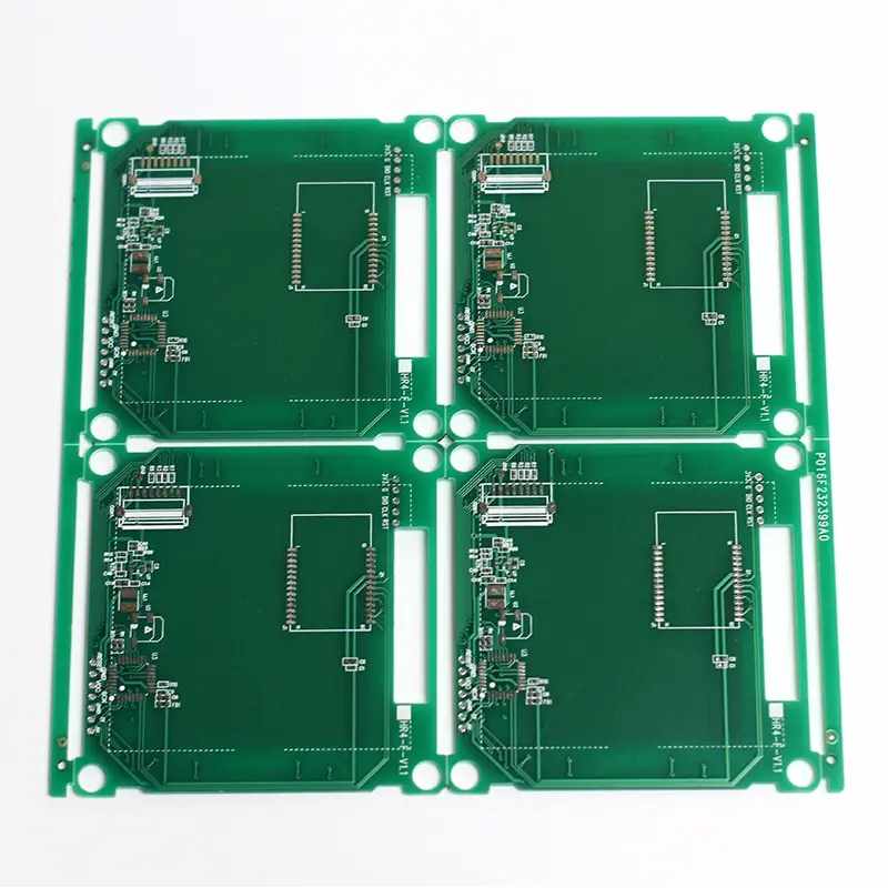
The low-cost method is to make a circle of grounding vias at 1/20 wavelength hole spacing around the PCB to form a grounding vias shield to prevent external radiation of TME waves.
For microwave circuit boards, the wavelength is further reduced. Because of the current PCB production process, the spacing between holes cannot be very small. At this time, the way that 1/20 wavelength spacing is used to drill shielding vias around the PCB has no obvious effect on the microwave board. At this time, the metallized edge wrapping process of PCB version is needed to surround the entire board edge with metal, so that microwave signals cannot be radiated from the PCB edge. Of course, The use of metal edge bonding process will also lead to a lot of increase in PCB manufacturing costs.
For RF microwave boards, some sensitive circuits and circuits with strong radiation sources can be designed with a shielding cavity welded on a PCB. When designing a PCB, "through hole shielding wall" should be added, that is, a grounded through hole should be added at the position where the PCB is close to the shielding cavity wall. In this way, relatively isolated areas are formed.
The design requirements of through hole shielding wall are as follows:
-There are more than two rows of vias;
-Two rows of vias are staggered;
-The spacing of vias in the same row should be less than λ/ 20;
-PCB resistance welding is prohibited at the crimping part between grounded PCB copper foil and shielding cavity wall.


Just upload Gerber files, BOM files and design files, and the KINGFORD team will provide a complete quotation within 24h.