
Professional PCB manufacturing and assembly
Building 6, Zone 3, Yuekang Road,Bao'an District, Shenzhen, China
+86-13410863085Mon.-Sat.08:00-20:00

PCB designers explain the role of PCB serpentine routing
PCB manufacturers, PCB designers and PCBA manufacturers will explain to you the role of PCB serpentine routing.
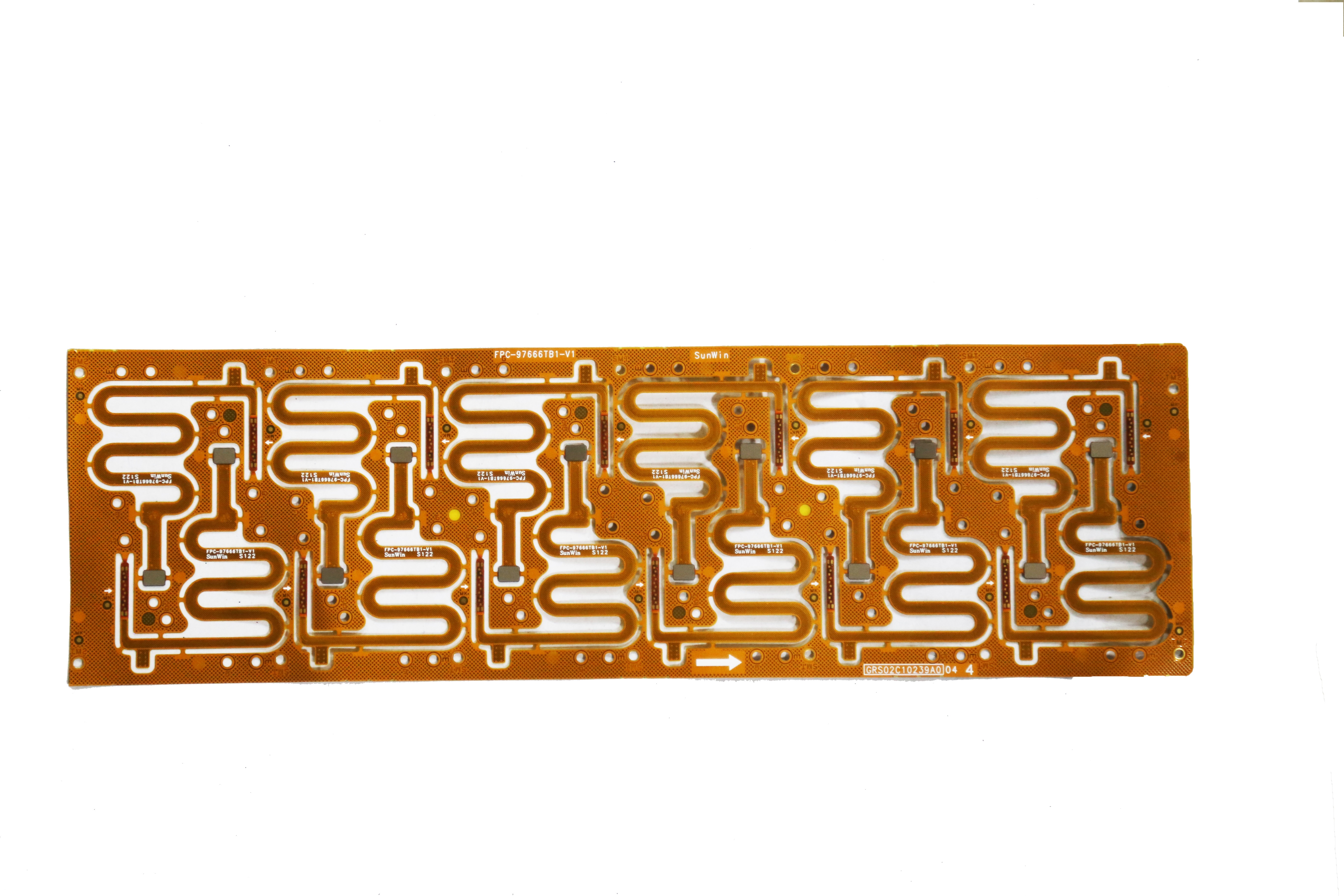
Any routing on the PCB will cause time delay to the high frequency signal when it passes through the signal. The serpentine routing is mainly used to compensate the parts with less delay in the "same group of related" signal lines. These parts usually have no or less logic processing than other signals; The most typical is the clock line, which usually does not need any other logic processing, so its delay will be less than other related signals.
The equal line length of high-speed digital PCB is to keep the delay difference of each signal within a range and ensure the validity of the data read by the system in the same cycle (when the delay difference exceeds one clock cycle, the data in the next cycle will be misread). Generally, the delay difference is required to not exceed 1/4 clock cycle, and the line delay difference per unit length is also fixed. The delay is related to the line width, line length, copper thickness, and board structure, However, if the line is too long, the distributed capacitance and distributed inductance will increase and the signal quality will be improved. Therefore, the clock IC pin is generally connected to the RC terminal, but the serpentine routing does not act as an inductance. On the contrary, the inductance will shift the phase of the higher harmonics in the rising element of the signal, causing the deterioration of the signal quality. Therefore, the serpentine line spacing is required to be at least twice the line width. The smaller the rise time of the signal, the more vulnerable to the influence of the distributed capacitance and distributed inductance
Because different applications have different functions, if the serpentine wiring appears in the computer board, it mainly acts as a filter inductor to improve the anti-interference ability of the PCB circuit. The serpentine wiring in the computer motherboard is mainly used in some clock signals, such as PCIClk and AGPClk, and it has two functions: 1. impedance matching; 2. Filter inductance. For some important signals, such as the HUBLink in the INTEL HUB architecture, there are a total of 13 HUBLinks running at 233MHz. They must be strictly equal in length to eliminate hidden dangers caused by time delay. Wire winding is the only solution. Generally speaking, the line spacing of serpentine routing is>=2 times the line width. The serpentine cable on the PCI board is designed to meet the line length requirements of the PCI 33MHzClock. If it is a LC filter with distributed parameters in ordinary PCB boards, it can also be used as the inductance coil of radio antennas, and short and narrow serpentine wires can be used as fuses
Supplement 1:
The use of serpentine line is indeed helpful to improve the stability of the main board and video card, eliminate the inductance of long and direct wiring when the current passes through, and reduce the crosstalk between lines, which is particularly obvious at high frequencies. Of course, you can achieve the same effect by reducing the density of wiring.
Conditional friends can observe the motherboard at hand. CPU socket -->Beiqiao chip, Beiqiao -->AGP slot, back of frequency generator, and memory DIMM slot are the places where serpentine cable is used intensively. The reason is that these devices work at high frequency and need stable current signal.
In PROTEL, you generally draw lines manually, and then make all lines to be set into one class. Select Tools/Equalize net lengths.
Supplement 2:
The main thing to reduce the crosstalk between lines is to increase the line spacing, which has nothing to do with snaking. Instead, the snaking line will lead to the crosstalk problem of the wire itself. Each part of the signal in the main version of the computer is very strict with the timing requirements, so it is necessary to match the length of each signal to meet the sufficient establishment and retention time. The snaking line is only related to the timing design, and has nothing to do with the integrity of high-frequency signals. Many foreign signal integrity works I have read, as well as Guildline from chipset manufacturers, do not require designers to adopt the serpentine routing method. Of course, there will be requirements for the length of the routing, but this only meets the timing specification. PCB manufacturers, PCB designers and PCBA manufacturers will explain to you the role of PCB serpentine routing.


Just upload Gerber files, BOM files and design files, and the KINGFORD team will provide a complete quotation within 24h.