
Professional PCB manufacturing and assembly
Building 6, Zone 3, Yuekang Road,Bao'an District, Shenzhen, China
+86-13410863085Mon.-Sat.08:00-20:00

Key points of LVDS signal design on PCB
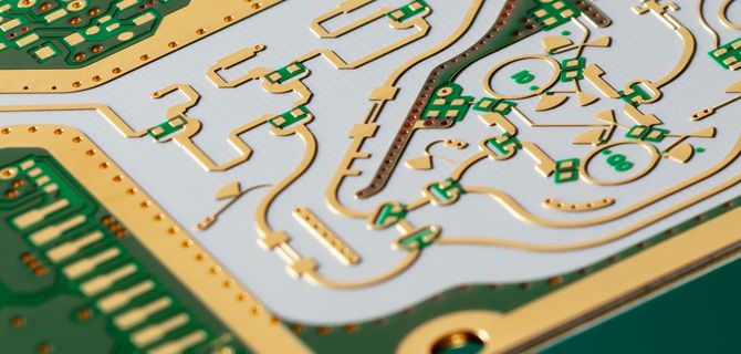
Design of Low Voltage Distribution System Signal PCB is not only a differential signal, but also a high-speed digital signal Therefore, no matter whether the LVDS transmission medium uses PCB board wires or cables, measures must be taken to prevent signals from reflecting on the media terminals, and electromagnetic interference should be reduced to ensure signal integrity It is not difficult to design high-speed differential circuit boards as long as we consider these elements in wiring The following is a brief introduction to the key points of LVDS signal design PCB board: 21 multilayer board layout The circuit board with LVDS signal is usually arranged as a multilayer board Because the LVDS signal is a high-speed signal, the adjacent layer should be a ground plane to mask the LVDS signal and prevent interference For low-density circuit boards, if the physical space conditions allow, place LVDS signals and other signals on different layers For example, in a four layer board, layers can usually be arranged as follows: LVDS signal layer, ground layer, power layer, and other signal layers 2.2 LVDS signal impedance calculation and control The voltage swing of LVDS signal is only 3.50mV, which is suitable for current driven differential signal operation In order to ensure that the signal is not affected by the reflected signal when propagating in the transmission line, the LVDS signal needs to control the transmission line impedance, which is usually 100++/- 10 Î ©. The quality of impedance control directly affects signal integrity and delay
PCB board

1. How to control the impedance of its PCB?
1.1 Determine wiring duct, parameters and impedance calculation LVDS is divided into outer microstrip line differential mode and inner stripline differential mode The impedance can be calculated by reasonably setting parameters and using relevant software Through calculation, the impedance value is proportional to the thickness of the insulating layer and inversely proportional to the dielectric constant, and the thickness and width of the wire
1.2 Follow the principle of parallel equidistant lines and close coupling After the line width and spacing are determined, the calculated line width and spacing shall be strictly followed when routing. The spacing between two lines must always remain constant, that is, they must be parallel (you can place the picture) At the same time, when calculating the line width and spacing, follow the tight coupling principle, that is, the line spacing of the difference pair is less than or equal to the line width When the two differential signal lines are very close, the current transmission direction is opposite, the magnetic fields cancel each other, and the electric fields couple with each other, so the electromagnetic radiation is much smaller Moreover, the two wires must be on the same layer to avoid layered wiring Because in the actual processing of PCB boards, the degree of lamination between layers is far lower than the etching accuracy of the same layer, and the dielectric loss in the lamination process cannot ensure that the distance between the differential lines is equal to the thickness of the interlayer medium, which will lead to the change of the differential impedance of the interlayer differential pair
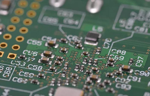
PCB board
1.3. Short and straight In order to ensure the signal quality, the LVDS differential pair track should be as short and straight as possible to reduce the number of vias in the wiring and avoid the differential pair wiring being too long and too many turns Try to use 45 ° or arc at the corner Avoid 90 ° turns Selecting LVDS between different differential line pairs does not limit the routing method Microstrip lines and striplines can be used, but it must be noted that there is a good datum The distance between different differential lines shall not be too small, and shall be at least 3-5 times of the distance between differential lines If necessary, add ground hole isolation between different differential pairs to prevent mutual crosstalk Keep the LVDS signal away from other signals as far as possible LVDS differential signals cannot be split across planes Although the transmission line across the segmentation will cause continuity in impact due to the layer of a reference plane (as shown in the figure, where GND1 and GND2 are adjacent to LVDS Ground plane) The distance between the matching resistance at the receiving end and the receiving pin should be as close as possible At the same time, the accuracy of matching resistor must be controlled For point-to-point topology, the impedance of the trajectory is usually controlled at 100 Ω), but the matching resistance can be adjusted according to the actual situation The degree of resistance is 1% - 2% Because according to experience, 10% impedance mismatch will produce 5% reflection
2. Simulation analysis of serial LVDS signal
The above analyzes the matters that must be paid attention to when designing LVDS signals Although the above rules are usually followed during PCB design, in order to improve the correctness and accuracy of design, the complete signal analogy of PCB must be carried out through analogy Get the crosstalk, delay, reflection and eye diagram waveform of the signal, so as to achieve the correct design The simulation process of signal integrity problem is to first establish the simulation model of components, and then conduct pre analogy to determine the parameters and constraints of the routing process Design the physical implementation phase according to the constraints, and conduct post simulation to verify whether the design meets the design requirements In the whole process, the nature of the model directly affects the analog results, and the simulation analysis methods used in the pre simulation and post simulation stages are also crucial to the simulation results. This design uses a higher order spice model The following describes the implementation process of simulation in this design in combination with the actual project
2.1 PCB stack setting
From the above analysis, it is known that PCB is closely related to signal coupling and impedance calculation Therefore, the stacking design must be carried out in PCB design, and then the signal impedance shall be calculated
2.2 Set DC voltage value
This step is mainly to specify the DC voltage value for certain specific networks (commonly power ground, etc.) These voltage values include the reference voltage information used by the model in the analogy process
2.3 Device settings
During Allegro simulation, Allegro divides devices into three categories: IC, connectors and discrete devices (resistance capacitors, etc.). Allegro will assign analog content to device pins according to device type. Discrete device and connector pin content is UPSPEC. IC pin content can be in, out, BI company, etc
2.4 Model allocation
The main models used in the board level high speed PCB simulation process includes equipment model and transmission line model The equipment model is usually provided by the equipment manufacturer The SPICE model with high precision is used to simulate and analyze the high-speed tandem signals The transmission line model is formed through simulation software modeling During signal transmission, the transmission line will highlight the problem of signal integrity. In summary, the ability of simulation software to model the transmission line directly affects the simulation results
2.5 SI inspection
The SI Audit function is used to check whether a particular network or a group of networks can be extracted for analysis. In general, we need to pay attention to the establishment of high-speed networks This design mainly aims at LVDS serial signal
2.6 Extract network topology
Extract the topological structure of the signal of interest from the PCB, generally including the drive end and the receiving end, as well as the transmission line and related matching resistors and capacitors It can be seen from the topology that the network passes through these paths, which will lead to the impact of signal transmission This article only takes the network topology diagram of one of the signals as an example: as shown in Figure 4:
2.7 View waveform
After the above related steps are set up for analogy Allegro can perform signal reflection analogy and crosstalk analogy, and eye diagram analysis is also required for differential lines Of course, the simulation is also divided into pre simulation and post simulation When using allegro to design PCB, it is necessary to modify the design in real time according to the simulation results to meet the requirements Because the analogy process is complex and the steps are tedious, I will not describe them one by one Two points should be noted in the wiring of differential pairs First, the length of the two lines should be as long as possible. The equal length is to ensure that the two differential signals are always opposite Reduce the polarity of common mode components The other is that the distance between the two lines (this distance is determined by the differential impact) must always be kept constant, that is, it must be kept parallel There are two kinds of parallel pipes. One is that the two wires run on two adjacent layers above and below (over under) Generally, the former has more parallel implementations Equal distance is mainly used to ensure the same differential impedance between them and reduce reflection The wiring method of differential pair shall be tight and properly parallel The so-called proper approach is because this distance will affect the value of differential impedance, which is an important parameter for designing differential pairs The need for parallelism is also to maintain the consistency of differential impedance If the two lines are suddenly far and near, the differential impedance will be inconsistent, which will affect signal integrity and timing delay The differential impedance and signal integrity of the differential pair can be analyzed from the analog S parameter diagram The key signal analog waveforms in this design are given below for explanation It can be seen from the analogy legend Figure 5 that the degradation index of S11 in the frequency domain is 0-3.0GHz, which is lower than -16.770db, and S22 (pin curve) is not worth than - 17db This shows that the differential impedance of the differential pair is close to the design quota, and the signal integrity is guaranteed
3. Conclusion
Through the above simulation analysis, it can be known that PCB can meet various requirements for high-speed LVDS signals in the design stage, and PCB production in actual situations also proves the correctness of the design The product runs stably and fully meets the requirements of PCI Express for high-speed data transmission and high reliability From the analysis in this paper, it can be seen that in the design of high-speed serial signals, not only the circuit design is considered, but also the circuit board design and simulation analysis are equally important. With the increasing frequency of the signal, the signal delay and crosstalk are affected Signal integrity and signal integrity become more and more complex At the same time, it becomes more and more difficult to control the influence of these factors In order to provide the correct guidance for the complex high speed PCB design and reduce the correction cycle to ensure The design is successful


Just upload Gerber files, BOM files and design files, and the KINGFORD team will provide a complete quotation within 24h.