
Professional PCB manufacturing and assembly
Building 6, Zone 3, Yuekang Road,Bao'an District, Shenzhen, China
+86-13410863085Mon.-Sat.08:00-20:00

Various PCB manufacturing methods and processes
1. Production method introduction PCB board
1.1 Method 1:
(1) Cut this coupler clad board to the size required for the circuit diagram
(2) Put the wax paper on the steel plate, use a pen to carve the circuit diagram on the wax paper in 1:1 ratio, cut the circuit diagram carved on the wax paper according to the size of the circuit board, and then put the cut wax paper on the printed copper plate Take a small amount of paint and talcum powder to make a suitable thin and thick printing material. Dip the printing material with a brush and evenly smear it on the wax paper. Repeat several times. The circuit can be printed on the printed board This prototype is reusable and suitable for small batch production
(3) Prepare a corrosion solution with 1 gram of potassium chloride and 40 ml of hydrogen acid with a concentration of 15%, and apply it on the circuit board for corrosion
(4) Wash the corroded printed board with water repeatedly. Wipe off the paint with banana water and wash it several times to keep the printed board clean without leaving any corrosive liquid Dry the hole with a layer of rosin solution
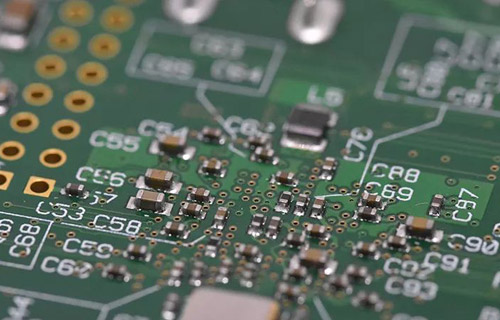
PCB board

1.2 Method 2:
(1) Drawing of the printing plate. Pads in the figure are represented by dots. The connection can be a single line, but the location is different The dimensions need to be precise
(2) Cut the printing plate according to the size of the printing plate to clean the copper foil surface
(3) Use carbon paper to copy the diagram to the printing board. If the circuit is relatively simple and the manufacturer has some experience in manufacturing circuit boards, this step can be omitted
(4) According to the specific conditions of the actual components, paste standard pre-cut symbols (pads) with different inner and outer diameters; Then, depending on the current, stick tape lines of different widths 1.50) and so on, buy the paper based material (black), and try not to use the plastic based (red) material Common specifications of adhesive tape are 0.3.0.9.1.8.2.3.3.7, etc All tissues are in millimeters
(5) Use a soft hammer, such as smooth rubber Tap a label, etc with plastic Make it completely adhere to the copper foil Focus on the corner of the line Lap joint In cold weather, use a heater to heat the surface to increase adhesion
(6) Put it into ferric chloride to cure, but it should be noted that the liquid temperature is not higher than 40 ℃ After corrosion, it shall be taken out and washed in time, especially if there are fine wires
(7) Punch holes, brighten copper foil with fine sandpaper, smear rosin alcohol solution, and dry it to complete production The quality of this PCB is very close to that of ordinary PCB The 0.3mm adhesive tape can pass between the two legs of the IC, which can greatly reduce the short circuit on the front of the circuit board, thus saving trouble Save time
1.3 Method 3:
Dissolve one part of the lacquerer sheet (ie shellac, available in chemical raw material stores) in three parts of an aqueous alcohol, and mix properly It can be used as a protective paint for circuit boards after a certain color is displayed and stirred evenly First, polish the copper clad laminate with fine sandpaper, and then use the duckbill pen in the drawing instrument (or the ink duckbill pen used to draw graphics on the compass) to draw the drawing The pen has a nut for adjusting the stroke thickness Adjustable, can borrow ruler The angle ruler draws a thin straight line, which is smooth Even without serrated edges, the surface is smooth The feeling of fluency; At the same time, you can also write Chinese characters in the free space of the circuit board English pinyin or symbol
If the concentration is too small, you can add a little varnish; If you can't drag the pen, it's too thick. You need to add a few drops of absolute alcohol It doesn't matter if the drawing is wrong. Just use a small stick (matchstick). Make a small cotton swab and dip it in a little anhydrous alcohol. You can easily erase it and redraw it After the circuit board is drawn, it can be etched in 3 ferric chloride solution It is also convenient to remove the paint after the circuit board is corroded Dip the cotton ball in anhydrous alcohol, and the protective paint can be wiped off The prepared protective paint should be stored in a small bottom (such as an ink bottom) sealed and stored Don't forget to close the bottle cap after use If the concentration becomes thicker next time, just add an appropriate amount of absolute alcohol
1.4 Method 4:
Paste the instant stick on the copper foil of the copper plate, then draw a circuit on the veneer, and then use a carving knife to carve on the veneer layer to form the required circuit, remove the non circuit part, and use ferric chloride for corrosion or current electrolysis This method can produce more ideal circuit board The corrosion temperature can be about 55 ℃, and the corrosion rate is faster Rinse the corroded circuit board with clean water, remove the notes on the circuit, make holes, wipe it clean, and then apply rosin alcohol solution for use
1.5 Method 5:
(1) According to the shape of the components used in the circuit schematic diagram and the size of the printed board area The position of components shall be determined according to the principle of big priority, filial piety first, the whole, and then the part, so that adjacent components in the circuit are placed nearby and arranged neatly and evenly
(2) The connecting wires between the components cannot turn at right angles at the corners and the intersection of the two lines When some wires cannot do this, consider printing wires on the back of the printed board, and then connecting them to the front circuit with pierced nails, or using additional insulated wires when welding components
(3) The distance between the input part and the output part is better to avoid mutual interference.
1.6 Method 6:
Radio hobbyists have struggled with making circuit boards. Now we introduce a "separate printing" method of making printed circuit board Methods as below:
(1) Print the circuit board diagram on 80 grams of copy paper at a ratio of 1:1 on the printer. You can also draw by hand, but the backing paper should be flat
(2) Find a fax machine, take out the fax paper in the machine and replace it with hot melt plastic film Put the circuit diagram at the entrance of the fax machine, and use the copy button of the fax machine to copy the circuit diagram on the hot melt plastic film At this time, the "Print Original" of the PCB is ready
(3) Use double-sided tape to flatly stick the drawn plastic film on the copper-clad plate. Note that it should be flat and wrinkle free, and the adhesive tape should not cover the melted part, otherwise the production effect of the circuit board will be affected
(4) Brush the paint evenly on the plastic film with a paintbrush. Note: You can't brush back and forth, but only in one direction Otherwise, the plastic film will wrinkle together and the lines on the copper plate will overlap After the circuit diagram is completed, carefully remove the plastic film At this time, the printed circuit board After drying, it will corrode If you want to print multiple pieces, you can make a wooden frame a little larger than the circuit board, place the screen flat on the wooden frame, and repair it Then use double-sided tape to stick the fixed plastic film under the screen Put the copper clad plate on the table, close the screen frame (the printed image and the copper clad plate should be aligned left and right), brush paint in one direction with a brush, and remove the grid frame The printed circuit board has been printed If it is defective, it can be modified with paint and bamboo chips In the above process, it should be noted that the hand force should be appropriate when painting If the paint film is too heavy, these lines are lace. If it is too light, the lines will break The plastic film must face upwards The method of printing part drawings is the same as above
2. Introduction to PCB process entry in PROTEL
Many founders feel that the Protel software itself is easy to learn and easy to use In order to promote this powerful EDA tool, software manuals, etc It has been published in China, but unfortunately, these readings are usually written for the software itself, which makes readers confused with PCB process There is little explanation for this concept In order to design PCB patterns that meet the requirements, you must first understand the general process of modern technology. Otherwise, PCB will be a closed door Generally speaking, printed boards are divided into single-sided, double-sided and multilayer boards The process of single-sided printing plate is relatively simple, usually including blanking screen printing corrosion removal of printing materials hole processing printing marking coating flux finished product The process of multilayer printed circuit board is more complex, that is, processing of inner layer data - processing of locating hole - surface cleaning treatment - making of inner layer wiring and pattern - corrosion - pre lamination treatment - pressing of inner and outer layer data layer - hole processing - hole metallization - making of outer layer pattern - electroplating of corrosion-resistant weldable metal - removing photosensitive adhesive - corrosion - gold plating of plug, shape treatment, hot melting, coating flux and finished product The process complexity of double-sided panel is between the two, which will not be described here
EMC/EMI Control Technology in PCB Design
Nov 08,2022


Just upload Gerber files, BOM files and design files, and the KINGFORD team will provide a complete quotation within 24h.