
Professional PCB manufacturing and assembly
Building 6, Zone 3, Yuekang Road,Bao'an District, Shenzhen, China
+86-13410863085Mon.-Sat.08:00-20:00

Summary of key points for manual assembly of the latest PCBA circuit board through-hole plug-in components in 2022
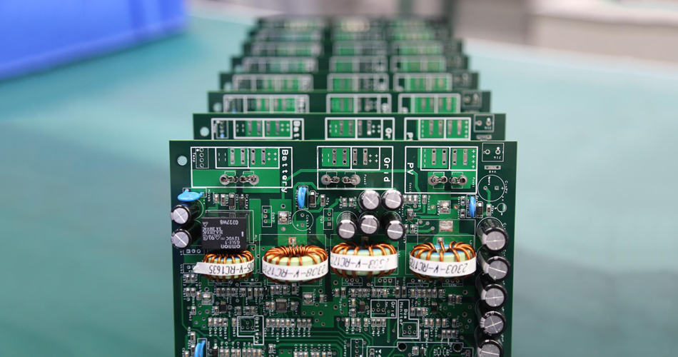
How much do you know about the insertion of electronic components on PCB? Now the insertion of electronic components is very particular, and the key points and principles to be paid attention to are also very complicated. Today we will introduce the insertion methods and process requirements of circuit board components.
The insertion of components is a process and procedure. In addition to affecting the orderly and beautiful arrangement of components on the installed circuit board, it is more important that the installation of components directly affects the installation quality of the circuit board. Therefore, there are strict requirements for the insertion of components.
(1) The installation and insertion of components should follow the principle of "big first, small second, low first, high second, inside first, outside first", which is conducive to the smooth installation and insertion.
(2) When the resistance element is installed horizontally, the mark number shall be upward and the direction shall be consistent. Those with low power can be installed and inserted close to the plane of the printed circuit board, while those with high power should be 2mm away from the plane of the printed circuit board, which is helpful for heat dissipation of components.
(3) When the capacitors, triodes and other components are installed and inserted stereoscopically, the lead wire cannot be kept too long, otherwise the stability of the components will be reduced; However, it should not be too short to avoid damage to components due to overheating during welding. Generally, it is 2mm away from the circuit board, and pay attention to the positive and negative polarity of the electrolytic capacitor and the pins of the triode.
(4) The insertion of components on the printed circuit board shall be evenly distributed, neatly arranged and beautiful, and shall not be inclined, crossed or overlapped. The shell of components and leads shall not touch each other, and a certain distance shall be reserved.
1. Commonly used wires are divided into wire and cable. Wire includes bare wire, insulated wire and electromagnetic wire. Cable consists of conductor, insulating layer, shielding layer and sheath. Different conductors are used in different occasions, so electrical factors, environmental factors and assembly process factors shall be considered when selecting conductors.
2. Insulating materials can be divided into inorganic, organic and mixed insulating materials according to their chemical properties. Performance indexes of insulating materials: resistivity, electric breakdown strength, breakdown voltage, mechanical strength, heat resistance, etc.
3. Common welding materials include solder, solder, and flux (flux and solder resist); Electric soldering iron is the main tool for manual welding. Reasonable selection and use of electric soldering iron is the basis for ensuring welding quality.
4. Magnetic materials are divided into soft magnetic materials and hard magnetic materials. The main characteristics of soft magnetic materials are high permeability and low coercivity. Under the effect of external magnetic field, the magnetic induction strength can quickly reach saturation. When the external magnetic field is removed, the magnetism will basically disappear and the remanence will be small. The main feature of hard magnetic materials is their high coercivity. After saturation magnetization, even if the external magnetic field is removed, the magnetic properties will remain stable for a long time.
5. The processing of insulated conductor is divided into cutting, stripping and twisting (multi strand wire, tin coating, cleaning, marking and other processes). Processing of insulated conductor and shield conductor ends.
6. The binding methods used are wire rope binding method, special wire binding and buckle connection method, gluing and bonding method, casing sleeve fitting method, etc.
7. The shape and structure of shielded conductor or coaxial cable are the same, and their processing methods are also the same, including processing of ungrounded wire end, processing of grounding wire end, and binding of wire end.
8. The forming methods of component lead mainly include special die forming, special equipment forming and simple processing and forming by hand with pointed nose pliers. Among them, mold manual forming is commonly used.
9. Before tin dipping, the lead of components shall be removed at a distance of 2-5mm from the root of the device. The time from removing the oxide layer to tin dipping shall not exceed one hour.
10. The plug-in forms of components can be divided into vertical plug-in, horizontal plug-in, inverted plug-in, horizontal plug-in and embedded plug-in.
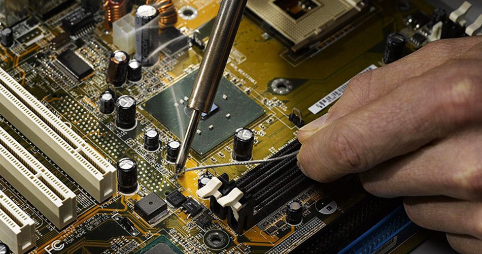
11. Five step operation method is often used for manual welding. Tips for manual welding:
① Surface treatment shall be carried out for weldments first.
② The element leads shall be tinned.
③ Do not overuse the flux.
④ Always rub the soldering iron head.
⑤ Solder bridges shall be provided for heating pads and components.
When welding the metallized hole on the double-layer circuit board, not only the pad should be wetted with solder, but also the hole should be wetted and filled, so the heating time for the metallized hole should be slightly longer.
11. There are three basic forms of welding between the conductor and the terminal block: winding welding, hook welding and overlap welding.
13. Manual desoldering methods and techniques:
Generally, there are not many pins of resistance, capacitor, diode, transistor and other components. These components can be directly touched by soldering iron. When the components with multiple leads need to be removed or the leads of the components are relatively hard although the number of leads is small, the self-made special tools can be used to remove welding and make a special soldering iron head.
14. Bonding is also called bonding. The three elements for forming a good bonding are: selecting the appropriate adhesive, treating the bonding surface and selecting the correct curing method.
The above is an introduction to the insertion methods and process requirements of circuit board components. I hope it can help you!
Manual assembly of PCBA SMT electronic products
Oct 26,2022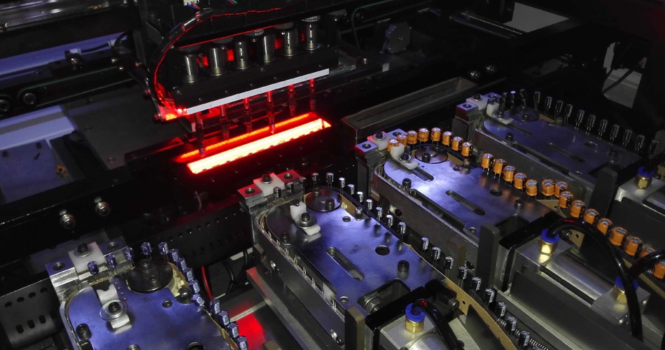


Just upload Gerber files, BOM files and design files, and the KINGFORD team will provide a complete quotation within 24h.