
Professional PCB manufacturing and assembly
Building 6, Zone 3, Yuekang Road,Bao'an District, Shenzhen, China
+86-13410863085Mon.-Sat.08:00-20:00

First, poor wetting
Poor wetting refers to the welding process of solder and substrate welding area, after wetting does not produce metal reaction, resulting in missed welding or less welding failure. Most of the reasons are polluted on the surface of the welding area, or stained with flux resistance, or caused by the formation of a metal compound layer on the surface of the joint, such as sulfide on the surface of silver, and oxide on the surface of tin. In addition, when the residual aluminum, zinc, cadmium, etc. in the solder exceeds 0.005%, the activity degree is reduced by the moisture absorption of the flux, and poor wetting can also occur. In wave soldering, if there is gas on the surface of the substrate, this fault is also prone to occur. Therefore, in addition to the implementation of appropriate welding techniques, anti-fouling measures should be taken on the surface of the substrate and the surface of the component, the appropriate solder should be selected, and a reasonable welding temperature and time should be set.
Two, bridge
Most of the causes of bridging are excessive solder or serious edge collapse after solder printing, or the size of the substrate welding area is out of line, SMD mounting offset, etc. In the stage of SOP and QFP circuits tending to micro-fine, bridging will cause electrical short circuit, affecting the use of products.
As corrective measures:
1. To prevent the welding paste printing when the edge is bad.
2. The size setting of the substrate welding area should meet the design requirements.
3. The mounting position of SMD should be within the specified range.
4. The wiring gap of the substrate and the coating accuracy of the solder resistance must meet the specified requirements.
5. Formulate appropriate welding process parameters to prevent mechanical vibration of the conveyor belt of the welding machine.

3. Cracks
When welded PCB is just out of the welding zone, due to the difference in thermal expansion of the solder and the part to be joined, under the action of quenching or heating, due to the influence of solidification stress or contraction stress, the SMD will basically produce micro-cracks, and the welded PCB must also reduce the impact stress on the SMD during punching and transportation. Bending stress.
In the design of surface mount products, it should take into account the reduction of the gap in thermal expansion, and correctly set heating and cooling conditions. Choose a good ductility solder.
Fourth, solder ball
The production of solder ball mostly occurs in the welding process of rapid heating and caused by the solder flying, in addition to the printing dislocation with the solder, the edge collapse. Pollution and so on are also involved.
Preventive measures:
1. Avoid excessive heating in welding, welding according to the set temperature process.
2. The printing edge of solder, dislocation and other bad products should be deleted.
3. The use of solder paste should meet the requirements without poor moisture absorption.
4. Implement the corresponding preheating process according to the welding type.
5. Suspension Bridge (Manhattan)
Bad suspension bridge refers to one end of the component leaves the welding area and leans upward or upright, the reason is that the heating speed is too fast, the heating direction is not balanced, the selection of welding paste, the preheating before welding, and the size of the welding area, the shape of the SMD itself, and the wettability.
Preventive measures:
1. The storage of SMD shall meet the requirements
2. The size of the substrate welding area length should be properly formulated.
3. Reduce the surface tension on the SMD end when the solder melts.
4. The printing thickness of solder should be set correctly.
5. Adopt a reasonable preheating method to achieve uniform heating during welding.
Analysis of PCB board in the production of red glue over wave soldering causes of missing parts
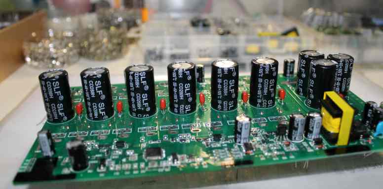
In the production process of PCB boards, many electronics companies use the red glue process to make SMT processes. In the process of using the red glue process, various components will encounter the problem of falling off, especially in the red glue process in the wave soldering process, the electronic component patch (especially the diode) often encounter the problem of falling off.
A detailed solution is given for the causes and solutions of over-wave soldering of components in the red glue process, as follows:
First, the PCB after the tin patch element drops
1. If the patch component and BCB's green oil (solder oil) fall off together, I will judge the PCB's incoming material problem (the adhesion of green oil is not enough).
2. Look at the PCB to see if there is scratch where the patch element falls off. Scratch where the PCB patch element falls off will also make the adhesion of the green oil insufficient, which can cause the patch element to fall after the PCB has passed the tin.
3, watch the PCB to see whether the patch components fall regularly, if it is fixed several patch components fall, you have to consider whether the hole of the red rubber steel mesh is blocked, the amount of red glue is too little.
4, the patch element fell off, the red glue is still well stuck on the above I decided that the patch element has a problem (the surface treatment of the patch element has a problem, such as release agent, affecting the adhesion of the red glue)
Second, the chip element to do the red rubber thrust experiment.
1. The chip elements fall off regularly, the holes of the red rubber steel mesh are blocked, and the amount of red glue is too little.
2, the patch element fell off, the red glue is still well stuck to the above, the surface treatment of the patch element has problems, such as release agents, affecting the adhesion of the red glue
3. If the patch component and BCB's green oil (solder oil) fall off together, I will judge the PCB's incoming material problem (not enough adhesion of green oil).
4, if the patch element does not fall regularly, you have to consider whether the viscosity of the red glue is not enough, such as the red glue expired, the return time of the red glue is not enough.
5, the patch component is dropped during transportation, such as (glass diode)
6, the chip element is the PCB patch after storage time is too long, generally seven days after the patch needs to be tin, if more than red glue will slowly lose viscosity.


Just upload Gerber files, BOM files and design files, and the KINGFORD team will provide a complete quotation within 24h.