
Professional PCB manufacturing and assembly
Building 6, Zone 3, Yuekang Road,Bao'an District, Shenzhen, China
+86-13410863085Mon.-Sat.08:00-20:00

Application of BGA Devices in Electronic Products
The large temperature difference △T in the chip range leads to the problem of different tin melting between rework and production,
which prompts manufacturers to try to obtain the reason for simultaneous tin melting. In order to avoid the impact of the humidity difference in the nozzle on the brazing,
when setting the reflow curve parameters, the solder joint should pass the solder melting point as soon as possible.
Flux application is very subjective and varies greatly from one technician to another.
Too much flux creates a liquid layer that can cause drift like CSP components during reflow; too little flux means there is not enough tack to keep the component in place when the hot air is started to flow. More recent research indicates that flux improvements on the BGA itself, rather than on the board solder joints, increase rework efficiency.
In order to solve the soldering problem, the lead-free BGA rework soldering curve needs to be optimized: increase the preheating temperature to speed up solvent volatilization and reduce voids;
lengthen the soaking stage time to ensure the wettability of solder joints and facilitate BGA to be heated evenly; speed up the cooling rate to benefit IMC Rapid formation improves the reliability of solder joints;
narrows the temperature difference between the upper and lower hot air to avoid deformation of the PCB substrate; reduces the peak temperature and prolongs the reflow time to avoid warping of the BGA due to excessive temperature.
Requirements for Nozzle/Heater
PCB preheating possible, automatic/programmable top/nozzle height adjustment, component placement force sensor on top,
hot air flow can be programmed to change size, series of nozzles with different sizes, nozzles prevent hot air flow from deviating to adjacent Components, nozzles with real-time vacuum sensors,
improved nozzle thermal capacity and control, development of interactive bottom heater controls, development of a universal PCB support system with automated calibration sequences.
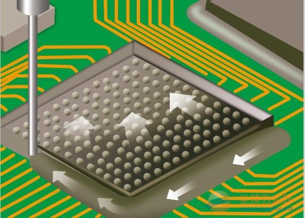
Adjust the airflow and heat transfer effect by controlling the height from the bottom of the nozzle edge to the PCB surface.
The CCGA package has a large heat capacity, and even within the CCGA package, different types of CCGAs have strong heat transfer capabilities
. During the manufacturing process,
it is necessary to ensure that the setting temperature of the nozzle and the bottom heater is the lowest and the heating time is the shortest when the solder joint reflow process is carried out.
The main parameters include: bottom heating temperature, nozzle temperature, nozzle position and air flow rate, etc.
Other components within 1 inch of the reworked component will not be reflowed
When the gap G between the nozzle and the plate surface is 0, the heating efficiency is the highest
There is a critical value Gopt between the nozzle and the board surface gap G. When G<Gopt, the edge solder point temperature TC4 is higher than the center solder point temperature TC3. When G=Gopt, the edge solder point temperature TC4 is equal to the center solder point temperature TC3; when G > Gopt, the edge solder joint temperature TC4 is lower than the central solder joint temperature TC3. For CCGA components, the optimum gap G is 0.5-2mm.
It is best to choose the temperature of the nozzle at 310°C, and the distance from the board surface is 1mm, which can not only prevent the temperature of the board surface from being too high, but also ensure that the molten residual solder can be absorbed well when the nozzle does not touch the board surface.
Bottom heater:
At 300-400°C, the heating efficiency is similar, and at lower than 300°C, the heating efficiency is lower. Therefore, the temperature below 300°C is suitable for preheating, and the temperature above 300°C is the choice that requires a higher heating rate.
For the rework process, a maximum temperature of 400°C is acceptable because the temperature at which the board is heated will not exceed the PCB glass transition temperature.
The bottom heating time and temperature contribute less to the heating rate and temperature of the rework area, while the nozzle provides most of the heat energy.
The peak temperature stay time should not be too long, otherwise Sn90Pb will soften, and the solder joint on the PCB side
The development of new components (solder column array, connector and socket) process to long-term stable work problems and printed board manufacturing process has brought many difficulties to rework, such as missing solder balls, uneven heating of large connectors, socket components It is not easy to repair, and the solder mask is damaged under the stress of repair, causing bridging and missing solder.
method
advantage
shortcoming
suction soldering iron
Inexpensive, excellent surface finish
Requires a well-developed soldering technology, which is easy to damage the pad and the shape of the solder paste
Solder Aspirator
Easy to use, excellent surface finish, inert gas process, capable of automation
Surface finish variability is technology dependent, pads may be lifted/solder mask damaged, automated processes are slow
Suction cup and soldering iron
Excellent surface finish for inert gas processes with minimal board damage
The operation is in the hot air at the top, and the rework position must be covered to prevent splashing
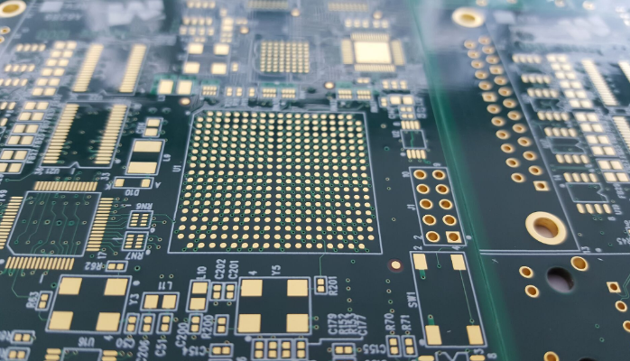
Surface mount packages are available in non-solder shield defined (NSMD) and solder shield defined (SMD), as shown in Figure
2. Compared with the SMD way, the NSMD way can strictly control the copper etching process and reduce the stress concentration points on the PCB, so this way should be preferred.
In order to achieve a higher ground clearance,
it is recommended to use a copper layer with a thickness of less than 30 microns. A copper clad layer with a thickness of 30 microns or more will reduce the effective ground clearance,
thereby affecting the reliability of the soldering.
Also, the width of the trace between the NSMD pad and the ground pad should not exceed two-thirds of the pad diameter. The pad sizes listed in Table 1 are recommended:
.in conclusion
As BGA devices are more and more widely used in electronic products, they have gradually become the mainstream technology in SMT.
The production of high-quality BGA devices and good BGA assembly process are quite technically difficult, and the control points must be grasped objectively and accurately.
Any assembly of PCB electronic components hopes to succeed at the first time, but often the rework process must be used because assembly defects cannot be completely eliminated. When rework is required,
the cost should be considered first. If the cost of the rework process is not worth the cost compared with the cost of the whole PCB, then there is no need for rework; if the cost is not an issue, the necessary rework should be reduced as much as possible to avoid damage to the printed board and affect the quality, thereby indirectly increasing the cost of the rework process.
The rework process is ostensibly a matter of component reassembly and seems to be related only to the component itself and the soldering method. In fact, warping of printed boards, damaged pads, wiring errors, and brazing misalignment are also factors that cause repairs.
Rework can use hand tools, semi-automatic equipment and automated equipment. The function of the rework tool is to remove the component and remount the component by melting the solder at the junction of the component lead and the pad. But in most cases, hand tools and semi-automatic equipment are more practical. The best equipment does not mean the best rework effect, it also depends on the skill of the rework operator.
Rework of surface mount components with a soldering iron is generally not feasible due to poor accessibility of surface mount components and small pads and leads. Moreover, due to the large number of solder joints in surface mount devices, the rework must be carried out simultaneously, but the basic principle is the same as for through-hole components.
It should be pointed out that when selecting rework tools/equipment, in addition to considering its versatility and reliability, the type of board and components to be reworked must be considered, such as multi-layer boards, ceramic chip capacitors, and highly sensitive QFP will require rework equipment It has a warm-up function and a visual system. Another consideration is the size of the printed board, the distance between traces and components. If a tool/equipment cannot meet the specifications of the board, it is useless to the assembler.
Reliability: CCGA > CBGA
Moisture Sensitivity: CCGA < CBGA
Power dissipation: CCGA > CBGA
Changing trends of crosstalk
Jun 06,2023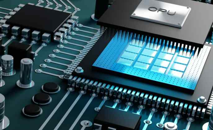


Just upload Gerber files, BOM files and design files, and the KINGFORD team will provide a complete quotation within 24h.