
Professional PCB manufacturing and assembly
Building 6, Zone 3, Yuekang Road,Bao'an District, Shenzhen, China
+86-13410863085Mon.-Sat.08:00-20:00

BGA Reliability Impact
Since flux directly affects electromigration and surface insulation resistance, cleaning is generally required after soldering, but flux cleaning at the bottom of BGA is a very tricky task, so it is recommended to use no-clean flux, so that cleaning is not necessary.
The underfill encapsulant of BGA can withstand mechanical shock, improve reliability and thermal cycle performance, and currently adopts two methods of full filling and four-point filling. Silicon-filled underfill encapsulants have better thermal cycling performance due to their lower CTE. Filler-free underfill encapsulants are less viscous and dense, are easier to spray, and flow quickly on the bottom of the device, allowing for the use of lower-cost equipment.
(1) High chip/package ratio and good reliability
(2) When the pad is large, the reliability is good (QFN)
(3) The reliability of thin plates is better than that of thick plates
(4) The reliability of soldering the heat dissipation pad to the PCB is better than not soldering (QFN)
(5) Influence of temperature cycle conditions: the damage caused by the same high temperature difference is greater than that at low temperature, and the number of failure cycles under high temperature variable rate conditions is lower than that under low temperature variable rate conditions
(6) The plastic packaging material meets two requirements: it must meet the reliability requirements of the minimum packaging level, that is, the moisture-sensitive level; it must ensure that the reliability of the packaging components mounted on the board meets acceptable requirements.
Ways to Improve Reliability
(1) Increase the height of the component from the board
(2) Solder ribbon formation (QFN)
1. BGA rework
2. BGA rework process
The BGA rework process generally includes component inspection, component removal, solder mask inspection after rework position cleaning, printing quality inspection after micro-stencil printing, pick-up and anti-alignment before starting reflow soldering after placing components.
When reworking ball grid display chips (such as BGA, CSP), you should be aware of the importance of process control for successful chip rework. The standard method is to simulate the production process as much as possible for the single chip removal and placement The process and reflow parameter settings, which means that when we rework a chip, we must heat a specific area of the circuit board. Brazing failures sometimes occur when heating indeterminate areas, although all parameter settings appear to be correct.
BGA rework is a last resort. It takes a long time to repair a piece of BGA, and it is necessary to have suitable solder balls and rework tools that can be accurately positioned. There are many methods for planting balls at present, but the success rate of planting balls is very low during actual operation. Even if it is repaired and then soldered, the chip has endured at least 4 reflow cycles, which will definitely affect the reliability of the soldering. Minimize or eliminate defects as much as possible, without repairing, this is the goal pursued.
The heat-resistant temperature of most semiconductor devices is 240-260°C. For the BGA rework system, the control of heating temperature and uniformity is very important. The chip supplier requires the maximum temperature of the chip surface to be 265°C, and the maximum temperature difference between the chip surface temperature, solder joint temperature and the bottom of the circuit board is changed from the traditional 10°C to 5°C after lead-free. The commonly used temperature for chip soldering is 240-250°C, which is close to the soldering temperature of 225-235°C, and the reflow time is shortened, which requires the rework system to quickly heat up and cool down.
BGA rework steps mainly include preheating circuit boards and chips; removing chips; cleaning pads; applying solder paste and flux; patching; reflow soldering.
(1) The main purpose of preheating the circuit board and chip is to remove moisture. If the moisture in the circuit board and chip is very small (such as the chip has just been unpacked), this step can be omitted.
(2) If the removed chip is not intended to be reused, and the PCB can withstand high temperature, a higher temperature (shorter heating cycle) can be used to remove the chip.
(3) Cleaning the pad is mainly to remove the flux and solder paste left on the surface of the PCB after the chip is removed, and a cleaning agent that meets the requirements must be used. In order to ensure the soldering reliability of BGA, generally the old residual solder paste on the pad cannot be used, and the old solder paste must be removed unless BGA solder balls are re-formed on the chip. Due to the small size of BGA chips, especially CSP (μBGA), the chip size is smaller and it is difficult to clean the pads. Therefore, when reworking CSP chips, if the surrounding space of CSP is small, no-clean flux should be used.
(4) Applying solder paste/flux on the PCB has an important impact on the rework results of the BGA. A newer method of solder paste deposition is to use a stencil to print solder paste directly onto the CSP or LGA, which is easy to master and provides good paste release and consistency. By choosing a stencil that matches the chip, it is easy to apply the solder paste to the board. When dealing with CSP chips, there are 3 types of solder paste to choose from: RMA solder paste, no-clean solder paste, and water-based solder paste. With RMA solder paste, the reflow time can be slightly longer, and with no-clean solder paste, the reflow temperature should be lower.
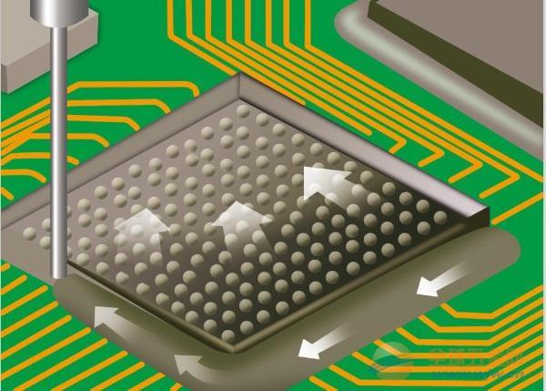
(5) The main purpose of the patch is to align each solder ball on the BGA chip with each corresponding solder joint on the PCB. Since the solder joint of the BGA chip is located in a part that cannot be observed by the naked eye, special equipment must be used for alignment.
(6) To ensure that the solder joints will not become brittle, good control of wetting and temperature is required, which requires better control of heating, heating and cooling rates, especially bottom heating. In the choice of heating method, hot air heating (convection method) is better than infrared heating (radiation method), and soldering iron (conduction method) cannot be used for heating.
3. BGA rework tools
The core issue of rework is how to achieve the best reflow profile. Once the circuit board structure and the distribution of components on the board are determined, there is only one optimal reflow soldering curve for the circuit board to achieve the optimal period of soldering. How to obtain the best welding conditions poses a direct challenge to craftsmen. Due to the limitations of variables such as equipment and auxiliary materials used in the rework process, craftsmen sometimes have to make various compromise choices.
Regardless of the heating method used by the equipment to feed back the control circuit, the single-chip rework equipment controls the welding process in a fully enclosed state. Since there are other components around the reworked chip, the current single-chip rework (no process control system) and single-chip rework system (full process control) in the world use open heating systems. Therefore, whether it is infrared, hot plate, infrared + hot plate, or hot air heating system, they all face the same technical requirements, that is, how to control the reflow soldering curve to approach or repeat the SMT reflow soldering curve in mass production.
(1) Infrared heating equipment
Lead-free soldering temperature is high and the process window is narrow, and the equipment performing lead-free soldering must have good cooling performance. Since the infrared heat source is usually a high-density ceramic heating body, although the system adopts temperature feedback control, because the heat source is inert and the infrared heating is radiative heating, even if the power is cut off, the heat radiation cannot disappear instantly, and damage to the chip will still occur. Temperature overshoot. Therefore, the rework system using infrared heating cannot control the cooling curve, that is to say, the formation of the reflow soldering zone cannot be well controlled.
The fatal flaw of infrared heating technology is the point heat source, and its heating principle is that directly heating an object will cause heat energy to penetrate the chip and then reach the solder ball. Since the device is made of materials of different colors and materials, the wavelengths of infrared rays absorbed by different parts are different, resulting in different temperatures in different parts of the device, which can easily cause overheating damage. Some people use infrared top heating on BGA. The experimental results show that the temperature at the BGA chip can reach 246.5°C, while the temperature of the solder ball is 189°C at this time, so it is easy to cause overheating damage. The table shows the absorption rate of different colors to infrared.
The latest infrared radiation selects a dark red radiator with a wavelength of 2-8 μm, which greatly reduces the problem of color sensitivity and improves temperature inhomogeneity. In order to reduce the unevenness of infrared heating, a metal heat sink is usually attached to the infrared heating source to overcome the defect of uneven heating (full metal plate or metal mesh with holes), but since the heating depends on infrared radiation, it is difficult to Fundamentally solve the problem of uneven heating. The use of high-density heat dissipation materials such as metals and ceramics can improve the uniformity of heating to a certain extent, but at the same time it will increase its thermal inertia.


Just upload Gerber files, BOM files and design files, and the KINGFORD team will provide a complete quotation within 24h.