
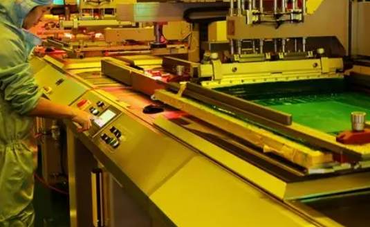
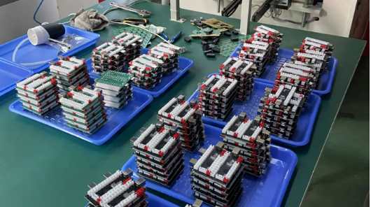
Professional PCB manufacturing and assembly
Building 6, Zone 3, Yuekang Road,Bao'an District, Shenzhen, China
+86-13410863085Mon.-Sat.08:00-20:00


The mismatch between decontamination/erosion/chemical copper deposition and the inadequacy of the individual steps are also worth considering. Those who have studied voids in pores strongly endorse the unified integrity of chemical treatment.
The traditional pretreatment sequence of copper deposition is cleaning, adjusting, activating (catalytic), accelerating (post-activating), and entering into the cleaning (leaching), preleaching, which is completely suitable for Murpiy principle. For example, the regulator, a cationic polyester electrolyte used to neutralize the negative charge on glass fibers, often has to be applied correctly to get the required positive charge: too little regulator, poor activation layer and adhesion; Too much adjustment agent, will form a layer of film resulting in poor adhesion of copper deposition; So that the wall of the hole pulls away. Regulator coverage is not sufficient, most likely to appear in the glass head. In metallography, hollow openings appear in glass fibers with poor copper coverage or no copper.
Other causes of the cavity in the glass are: insufficient glass etching, resin etching too much, glass etching too much, insufficient catalysis, or the activity of the copper sink is not good. Other factors affecting the coating of Pd activated layer on pore wall include: activation temperature, activation time, concentration, etc. If the cavity is on the resin, there may be the following reasons: manganate residue from the decontamination step, plasma residue, inadequate adjustment or activation, and low activity of the copper sink.
2. Cavities in holes related to chemical copper deposition
When viewing the holes in the hole, always look at whether there is a problem in the chemical tank, also look at the chemical copper pretreatment tank, but also cover the common problem of chemical copper, copper plating, lead/tin tank.
In general, we can understand that bubbles, solids (dust, cotton) or organic muck, dry film may hinder deposition of bath or activation solution. There are extraneous and internally generated bubbles. Foreign bubbles may sometimes be plate into the slot, or oscillation into the through hole. The natural bubble is caused by the reaction of hydrogen in the chemical copper solution, or the cathode to produce hydrogen or anode to produce oxygen in the electroplating solution.

Cavitation caused by bubbles has its own characteristics: it is often located in the center of the hole, and is symmetrically distributed in metallography, that is, there is no copper in the same width range to the face wall. If there are bubbles on the surface of the hole wall, they appear as small pits, and the holes are spicelike around them. An irregularly shaped cavity caused by dust, cotton or oily film. Some particles that interfere with plating or activation deposition are also coated with the coated metal. Non-organic particles can be analyzed by EDX and organic matter can be examined by FTIR.
The research on avoiding bubbles has been extensive. There are many influencing factors, such as cathode movement swing amplitude, spacing between plates, vibration swing and so on. The most effective methods to prevent bubbles from entering the hole are vibration and collision. It is also very important to increase the spacing between plates and the moving distance of the cathode. It is almost useless to stir the air in the chemical sedimentation tank and impingement or vibration of the activated tank. In addition, it is also very important to increase the wettability of chemical precipitation copper and avoid bubbles at the pre-treatment tide level. The surface energy of the bath is related to the size of the hydrogen bubble before it runs out of the hole or bursts. It is obviously hoped that the bubble will be excluded from the hole before it becomes larger, so as not to hinder the solution exchange.
3. Holes related to dry film
A. Feature description
Orifice or Rim voids (Rim voids) are voids located close to the surface of the plate. They are often caused by corrosion inhibitors located in the holes. They are approximately 50-70 microns wide from the surface. The cavity caused by chemical copper, electroplated copper, lead/tin plating is located in the center of the hole. The holes in the Barrel cracks also have different physical characteristics than those caused by dry film.
The hole mouth or hole edge cavity is due to the corrosion resistance into the hole, the development is not removed, it prevents copper, tin, solder plating, corrosion resistance is removed when the film is removed, chemical copper is etched away. Generally, it is difficult to find the corrosion inhibitor in the hole after development. The location of the cavity and the width of the defect are the main basis for judging the cavity at the orifice and the hole side. Why does the resist flow into the hole? The air pressure in the hole covered by resist is 20% lower than the atmosphere. The air in the hole is hot when the film is applied, and the air pressure decreases when the air is cold to room temperature. The air pressure causes the resist to flow slowly into the hole until development.


Just upload Gerber files, BOM files and design files, and the KINGFORD team will provide a complete quotation within 24h.