
Professional PCB manufacturing and assembly
Building 6, Zone 3, Yuekang Road,Bao'an District, Shenzhen, China
+86-13410863085Mon.-Sat.08:00-20:00

I. Assembly and welding of SOP and QFP.
1. Choose a soldering iron head with grooves, and set the temperature at about 280 Y, which can be changed appropriately according to needs.
2. Place SOP or QFP on the PCB with a vacuum pen or insert so that the pin of the device is aligned with the pad on the PCB.
3 Solder the diagonal pins of SOP or QFP to the pad with solder to secure the device.
4. Apply flux to the pins of SOP or QFP.
5. Use a damp sponge to remove oxides and residue from the tip of the soldering iron.
6. Apply an appropriate amount of solder to a pad with an electric soldering iron.
7. Apply solder in the groove of the soldering iron head.
8. Gently touch the groove surface of the soldering iron head to the top of the device and slowly drag it to weld the pin.
2. Assembly and welding of PLCC.
1. Choose a knife or shovel shaped iron head, and set the temperature at about 280 dragons, which can be changed appropriately according to needs.
2. Place the PLCC on the printed circuit board with a vacuum pen or instrument, so that the device pins are aligned with the pad on the printed circuit board.
3. Solder the diagonal pins of the PLCC to the pad with solder to secure the device.
4. Brush the PLCC pins with flux.
5. Use a damp sponge to remove oxides and residue from the tip of the soldering iron.
6. Weld the pins on the four sides of the PLCC to the pad with the soldering iron head and the soldering wire.
2.SMT (surface mount technology) manufacturing process
Have you ever wondered how your washing machine goes into different functional modes at the touch of a button? The secret behind it is the PCBA printed circuit board component.
In today's life, the motor is not only a cable and single function equipment, but also a variety of functions of the "assistant".
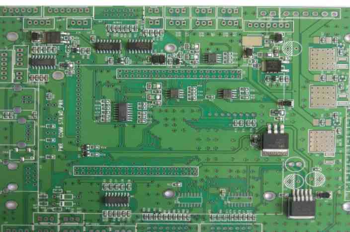
PCBA achieves this by clustering different kinds of electronic components onto a small area of substrate called a PCB, thus providing circuits that can perform complex and multifunctional tasks.
Now it's time for today's talk
What is SMT?
SMT, short for Surface mounting technology, is a method of attaching electronic components to the surface of a PCB.
Basically, it is welded to the plate by reflow soldering the SMC (surface mounted assembly).
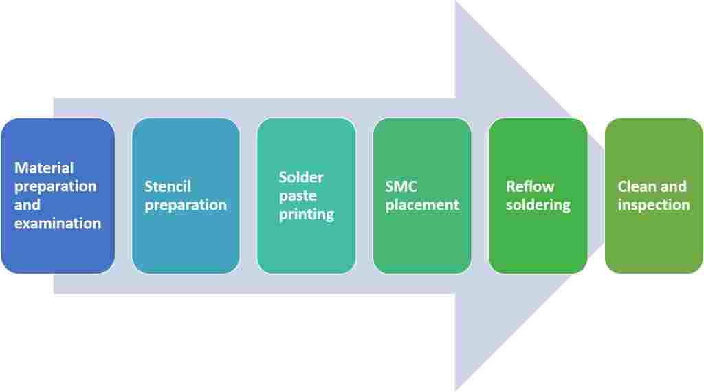
SMT manufacturing process

SMT process flow chart
1. Material preparation and inspection
Prepare SMC and PCB and check for defects. PCBS usually have flat, usually tin-lead, silver, or gold non-porous, brazed pads called pads.
2. Obtain a template
The template is used to provide a fixed position for solder paste printing. It is produced according to the design position of the pad on the PCB.
3. Solder paste printing
Solder paste, usually a mixture of flux and tin, is used to attach pads on SMC and PCBS. It uses a scraper applied to a PCB with a template at an Angle of 45°-60°.
4. SMC placement
The printed PCBS then go to the pickup and drop machine, where they are placed on a conveyor belt and electronic components are placed on top.
5. Reflow welding
Welding furnace: After placing the SMC, the plates are transported to the reflow furnace.
Preheating zone: The first zone in the oven is the preheating zone, where the temperature of the plate and all the components increases gradually at the same time. The temperature in this section rises at a rate of 1.0℃-2.0℃ per second until it reaches 140℃-160℃.
Hot zone: Hold the plate at 140℃-160℃ for 60 to 90 seconds.
Reflux zone: The circuit board then enters the zone where the temperature rises at a rate of 1.0℃-2.0℃ per second to a peak of 210℃-230℃ to melt the tin in the solder paste and bond the component leads to the solder pad of the PCB. The surface tension of the molten solder helps to hold the assembly in place.
Cooling Zone: An area where solder is guaranteed to freeze at the outlet of the heating zone to avoid joint defects.
If the board is double-sided, the printing, placement, and reflux process can be repeated by using solder paste or glue to hold the assembly in place.
6. Cleaning and inspection
Clean the circuit board after welding and check for defects. Rework or repair defects and store products. Common equipment associated with SMT includes magnifying glass, AOI (automatic optical inspection), flying needle tester, X-ray machine, etc.
This is our position. If you would like to learn more about SMT, please leave a comment below or contact us. We would love to hear from you!


Just upload Gerber files, BOM files and design files, and the KINGFORD team will provide a complete quotation within 24h.