
Professional PCB manufacturing and assembly
Building 6, Zone 3, Yuekang Road,Bao'an District, Shenzhen, China
+86-13410863085Mon.-Sat.08:00-20:00


Detailed knowledge of BGA component assembly and repair
Ball grid array (BGA) devices have undeniable advantages. But some problems in this technique are still for further discussion, and it cannot be realized immediately due to the difficulty of trimming the soldered end. BGA interconnect integrity can only be tested by X-ray or electrical test circuit methods, both of which are expensive and time-consuming.
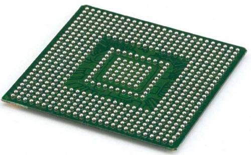
The two most common types of BGA packages are Plastic BGA (PBGA) and Ceramic BGA (CBGA). PBGAs have eutectic solder balls, typically 0.762 mm in diameter, that collapse into 0.406 mm high solder joints between the package and PCB during reflow (typically 215°C). CBGA uses non-melting solder balls on components and printed boards (in fact, its melting point is much higher than the temperature of reflow soldering), the diameter of the solder balls is 0.889mm, and the height remains unchanged.
assembly problem
The great advantage of BGA assembly is that if the assembly method is correct, its yield rate is higher than that of traditional devices. This is because it has no leads, which simplifies the handling of the component and therefore reduces the possibility of damaging the device.
The BGA reflow soldering process is the same as the SMD reflow soldering process, but BGA reflow soldering requires precise temperature control and the establishment of an ideal temperature profile for each component. Additionally, most BGA devices can self-align on pads during reflow soldering. Therefore, from a practical point of view, BGAs can be assembled with equipment that assembles SMDs.
However, since the solder joints of BGAs are invisible, the application of solder paste must be carefully observed. The accuracy of solder paste application, especially for CBGA, will directly affect the assembly yield. SMD device assembly can usually tolerate low yield because of the fast and low cost of rework, but BGA devices do not have this advantage. To improve first-time yields, many high-volume BGA assemblers have purchased inspection systems and sophisticated rework equipment. Pre-reflow inspection of solder paste application and component placement is more cost-effective than post-reflow inspection, which is difficult and expensive.
Solder paste should be selected carefully because the composition of solder paste is not always suitable for BGA assembly, especially PBGA assembly. Suppliers must ensure that their solder paste does not form solder joint voids. Likewise, if water-soluble solder paste is used, care should be taken in selecting the package type.
Since PBGA is sensitive to moisture, pretreatment measures should be taken before assembly. It is recommended that all packages be fully assembled and reflow soldered within 24 hours. Putting the device in the antistatic protective bag for a long time will damage the device. CBGA is not moisture sensitive, but care is still required.
repair
The basic steps of rework BGA are the same as rework traditional SMD:
Create temperature profiles for each component;
remove components;
Remove residual solder paste and clean the area;
Place the new BGA device. In some cases, BGA devices can be reused;
Reflow soldering.
Of course, each of the three main types of BGAs requires slightly different adjustments to the process. As with all BGAs, the establishment of a temperature profile is very important. Do not attempt to omit this step. Technicians can find it difficult to remove solder paste residue if they do not have the proper tools and training themselves. Too frequent use of a poorly designed desoldering braid, coupled with a poorly trained technician, can damage the substrate and solder mask.
Create a temperature profile
Compared with traditional SMD, BGA has much higher requirements on temperature control. The entire BGA package must be heated step by step to reflow the solder joints.
If the temperature, ramp rate, and hold time (2°C/s to 3°C/s) are not strictly controlled, reflow soldering will not occur simultaneously and may damage the device. Establishing a stable temperature profile for BGA removal takes some skill. Designers do not always have the information for each package, and trying methods can cause thermal damage to the substrate, surrounding devices, or floating pads.
Technicians with extensive BGA rework experience rely primarily on destructive methods to determine the proper temperature profile. Drill holes in the PCB to expose the solder joints and attach thermocouples to the solder joints. In this way, a temperature profile can be established for each monitored solder joint. The technical data shows that the establishment of the printed board temperature curve is based on a printed board fully loaded with components, using a new type of thermocouple and calibrated recording components, and using the high and low temperature areas of the printed board. A thermocouple is installed. Once a temperature profile has been established for the substrate and BGA, it can be programmed for repeated use.
Using some hot air rework systems, BGAs can be removed with relative ease. Typically, hot air is ejected from the nozzle at a temperature (determined by a temperature profile) to reflow the solder paste without damaging the substrate or surrounding components. Nozzle types vary by equipment or technician preference. Some nozzles flow hot air over the top and bottom of the BGA device, some move the hot air horizontally, and some spray the hot air over the BGA. Others prefer to use shrouded nozzles, which focus the hot air directly on the unit, protecting surrounding equipment. It is important to maintain the temperature when removing the BGA. The key is to preheat the bottom of the PCB to prevent warping. BGA removal is multi-point reflow, so skill and patience are required. also,
Cleaning and installation location
The rework area should be cleaned prior to BGA installation. This step can only be done manually, so the skill of the technician is very important. If the cleaning is not sufficient, the new BGA will not reflow normally, and the substrate and solder mask may also be damaged beyond repair.
When reworking BGAs in large quantities, the commonly used tools are desoldering irons and hot air desoldering devices. The hot air desoldering device first heats the surface of the pad, and then uses a vacuum device to suck away the melted solder paste. Desoldering irons are easy to use, but require skilled personnel to operate. Desoldering irons can easily damage printed boards and pads if used incorrectly.
Many assemblers prefer to use a desoldering braid when removing residual solder paste. With the proper weave and method, the removal process is quick, safe, efficient and inexpensive.
Using the tin removal braid requires some skill, but it is not difficult. Touch the solder paste to be removed with the soldering iron of choice and the braid so that the solder wick is between the tip of the soldering iron and the substrate. Direct contact of the soldering iron tip with the substrate may cause damage. Solder Paste-Solder Core BGA Removal Braid is designed to remove residual solder paste on BGA pads and components without damaging the solder mask or exposed traces. It optimally transfers heat to the solder joints through the braid, minimizing the possibility of pad displacement or PCB damage.
Since the core is very flexible in use, there is no need to drag the core to avoid heat damage. Instead, place the solder wick between the substrate and the tip of the iron, heat for 2 to 3 seconds, then lift the braid and iron up. Lifting instead of dragging, the braid minimizes the risk of damaging the pad. The braid removes all residual solder paste, eliminating the possibility of bridging and shorting. After removing residual solder paste, clean the area with a suitable solvent. Residual flux can be removed with a brush. For proper reflow soldering of new devices, the PCB must be clean.


Just upload Gerber files, BOM files and design files, and the KINGFORD team will provide a complete quotation within 24h.