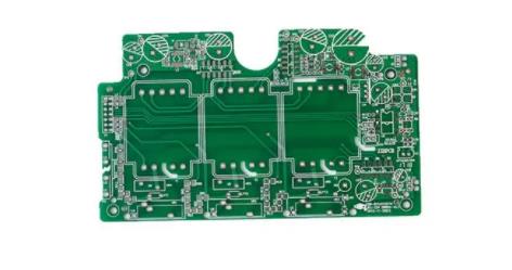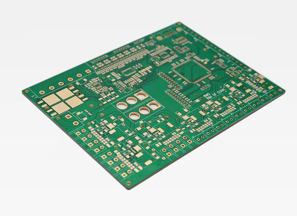
Detailed explanation of preferred selection of 77GHz radar antenna PCB board
Circuit board manufacturing, circuit board design, PCBA processing manufacturers explain to you the preferred selection of 77GHz radar antenna PCB board
With the development of science and technology, 77GHz microwave radar has been gradually applied in the market, such as automobile collision avoidance, UAV collision avoidance, security monitoring, etc. Due to its high frequency, short wavelength and wide operating frequency band, it has the advantages of small product size, long detection distance, high accuracy, and is relatively less affected by weather changes compared with similar products of 24GHz radar and other frequencies. It is precisely because of the characteristics of its wave length and the enhanced convergence effect that more attention should be paid to the selection of PCB materials for radar antennas and microwave RF parts.

Generally speaking, in the commercial and civil fields, RO3003PTFE ceramics from ROGERS, an international famous microwave material manufacturer, are generally recommended as PCB materials for 77GHz radars, mainly because of their good dielectric constant stability, low insertion loss and machinability of the plates. When 0.5 oz electrolytic copper foil is used and the dielectric thickness is 10 Mil, the equivalent dielectric constant of the 50 ohm microstrip line is 2.69, the dielectric loss is 0.11 dB/cm, the copper loss is 0.35 dB/cm, and the overall loss is 0.46 dB/cm.
In some cases, such as the use of high gain antennas, the size of the product will be relatively large, and the R&D personnel will feel that this loss still cannot meet the requirements of the system design. In this case, Rogers RO3003PTFE ceramic is still recommended as PCB material. However, it is recommended to use "calendered copper" for the attached copper foil. Compared with electrolytic copper foil, it has better surface roughness and can better reduce copper loss. Taking 0.5 oz copper foil as an example, the surface roughness of rolled copper is reduced from 1.8 um (RMS) to 0.3 um (RMS) compared with electrolytic copper. The equivalent dielectric constant of the 50 ohm microstrip line is 2.65, the corresponding copper loss is reduced from 0.35 dB/cm to 0.13 dB/cm, and the overall loss is reduced from 0.46 dB/cm to 0.24 dB/cm.
The above data is calculated by the software MWI2017 provided by Rogers, which considers a relatively ideal environment. Compared with the actual loss of the actually completed PCB, there are still some differences, mainly due to the impact of PCB processing technology and precision. How to reduce this impact and make it meet the original expectations of the designer, welcome to discuss with us. PCB manufacturers, PCB designers and PCBA processors will explain the selection of 77GHz radar antenna PCB boards.


