
Professional PCB manufacturing and assembly
Building 6, Zone 3, Yuekang Road,Bao'an District, Shenzhen, China
+86-13410863085Mon.-Sat.08:00-20:00

In recent years, the regulations on the layout and routing of pcb have become more and more complicated. The total number of transistors in integrated circuit chips still needs to increase continuously at the rate predicted by the Moore's law, which further promotes the rapid speed of components and the reduction of each single pulse along the gain value. In addition, the number of pins has also become more and more - usually up to 500~2000 pins. All of these are difficult problems in the design of pcb, such as relative density, clock and its crosstalk.
Two years ago, there were only a few "critical" connection points (net) on the vast majority of PCBs, which generally meant that some pipe bundles were encountered at the impedance, length, gap and other levels. The pcb design staff generally carried out manual PCB wiring to this kind of wiring first, and then used manual software to conduct large-scale full-automatic wiring to all power circuits. Nowadays, there are often 5000 or even a large number of connection points on pcbs, and more than 50% of them belong to critical connection points. Because of the pressure of time to market, it is impossible to choose manual wiring. In addition, not only the total number of critical connection points has increased, but also the linear combination of each connection point is increasing.
This kind of linear combination is mainly caused by the correlation of main parameters and the increasingly complicated design regulations. For example, the distance between two wiring lines will be an culvert number related to the working voltage of the connection point and the raw materials of the pcb circuit board. The reduction of large digital IC gain value will harm the design of both high clock rate and low clock rate. Because of the rapid creation and maintenance time caused by a single pulse, In addition, as a key part of the overall design of high-speed power supply circuit, the interconnection timing is also critical to the low-speed gear design.
If the circuit board is designed a little larger, some of the above problems will be easier to handle, but the current development trend is just the opposite. Because of the regulations on interconnection time and high density packaging, the circuit board has continued to shrink, resulting in a high density power circuit design. In addition, it is necessary to follow the practical design standards. The reduction of gain value coupled with this practical design standard makes the crosstalk noise problem more and more prominent, while the spherical grid array and other high-density packages themselves will also aggravate crosstalk, power switch noise, and ground wire bounce back and other problems.
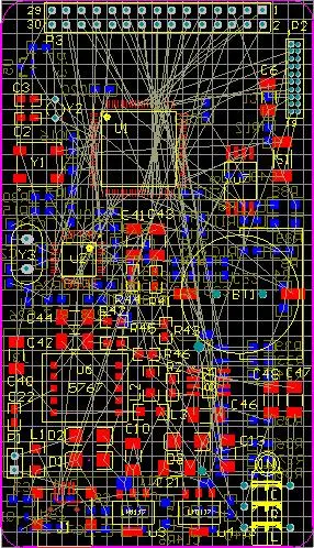
PCB design
Limitation of fixed fixed tube bundle
The traditional way to deal with this problem is to convert the electrical equipment and processing technology regulations into the main parameters of fixed tube bundles based on work experience, default values, data tables or calculation methods. For example, when PCB technical engineers design circuits, they may first determine a rated impedance, and then "estimate" a graphical limit of the rated value that can achieve the required impedance according to the final processing technology regulations, or use the measurement report or arithmetic program process to detect the impact, and then calculate the long short linear combination.
In this way, a complete set of work experience data information must be designed as the basic and specific guidance standard for the pcb design staff, so that this data information can be used when using the fully automatic and reasonable layout and routing special tools for design. The difficulty of this method depends on that the work experience data information is only a general standard. In most cases, they are all appropriate, but in some cases, they fail or cause incorrect results.
The deviation caused by this kind of method will be discussed in the case of clear impedance above. Elements related to impedance include the electrolytic dielectric characteristics of circuit board materials, copper berth height width ratio, the spacing between each layer and the ground/power supply layer, and the graphic boundary. Because the first three main parameters are generally determined by the production process, PCB designers generally manipulate impedance by the graphic boundary. Because the distance from each route layer to the ground or power supply layer is different, it is obviously incorrect to use the same work experience data information for each layer. In addition, the PCB production process or PCB characteristics selected in the whole process of development and design will change at any time and anywhere, so the problems will continue to be more complex.
In most cases, this kind of problem will be exposed in the sample preparation process. Generally, after finding the problem, it will be dealt with according to the repair of pcb circuit board or the re development of board design. The cost of doing so is relatively high, and the repair will often continue to create additional problems that must be further adjusted. Finally, the loss of earnings due to delayed listing time is far higher than the adjustment cost. Basically, every electronic device manufacturer is confronted with such a problem, which ultimately comes down to the fact that the traditional pcb design mobile phone software cannot closely follow the specific conditions of the current provisions on the characteristics of electrical equipment. In this point, it is not as simple as the working experience data information of mechanical equipment design.
Solution: Parametric tube bundle
At this stage, mobile phone software dealers try to solve this problem according to the method of improving main parameters in linear combination. The most excellent area of this type of method depends on the index value of mechanical equipment that can fully describe the characteristics of various internal electrical equipment. If it is added to the pcb design, the mobile phone design software can use this information to manipulate the special tools for fully automatic and reasonable layout and wiring.


Just upload Gerber files, BOM files and design files, and the KINGFORD team will provide a complete quotation within 24h.