
Professional PCB manufacturing and assembly
Building 6, Zone 3, Yuekang Road,Bao'an District, Shenzhen, China
+86-13410863085Mon.-Sat.08:00-20:00

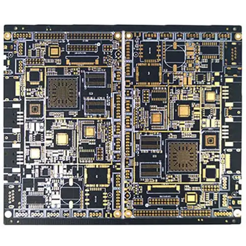
Stray capacitance is often used in electronic circuit of PCBA. Stray capacitance may exist between conductors on PCB, prefabricated circuit boards without components, PCBA, boards with components installed, and SMD component kits in component packaging (especially IC). Stray capacitance is one of the inherent physical properties of electronic circuits and circuit boards.
pcba

1. Remove inner ground plane
Since the ground plane will increase capacitance with adjacent conductors due to proximity, it is helpful to delete the inner ground plane to increase the distance, which will minimize the capacitance effect. This must be weighed against the benefits of minimizing EMI when the ground plane is adjacent to the signal plane.
2. Use Faraday Shield
Faraday shielding is a grounding trace or plane placed between two traces to minimize the capacitive effect between them, and like other shielding structures, it can effectively reduce stray capacitance.
3. Increase space between adjacent traces
Another effective mitigation technique is to increase the spacing between adjacent traces. As the capacitance decreases with the increase of distance, this is a very good method that can be applied.
4. Minimize the use of vias
Through hole is the key factor to make compact and complex PCB possible. However, excessive use may increase parasitic capacitance problems. For example, stray capacitance. This PTH coupling can be reduced by eliminating annular rings around vias on unconnected layers and minimizing the number of vias from the assembly. Such as BGA.
Principle of PCB Splitter
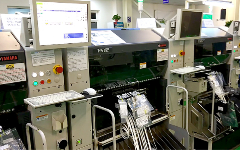
When PCB boards are divided, they are traditionally divided manually. This method has a relatively fast time effect. However, due to the difference in force and separation angle, it is easy to cause damage to PCB electrical circuits, parts and tin tracks. At this time, PCB board splitter came into being and became the SMT standard operation mode.
Principle of PCB Splitter
1. Before board splitting, first confirm whether the board splitting program edited by the engineer is correct. When an engineer edits or invokes a previously used program, it is necessary to preview and check it. After checking that the procedures of the left and right workbenches are correct, the engineer can process one piece on the left and one piece on the right for confirmation. After confirmation, the operator can operate by himself.
2. Put the PCB board to be punched into the fixture, define the direction and front and rear sides of the board, put it into the fixture, gently press the positioning column of the positioning fixture of the board, confirm whether it is in place, then cover the sub board fixture, and press the left or right green button. At this time, the worktable will automatically enter the plate splitting position.
3. Click the preview button of PCB software, the button is red, and observe whether each cutting position is correct. After viewing and checking, click the stop button on the software first. After a few seconds, the color turns green and automatically changes to the processing button, and the workbench automatically exits. Click the processing button on the software to start processing.


Just upload Gerber files, BOM files and design files, and the KINGFORD team will provide a complete quotation within 24h.