
Professional PCB manufacturing and assembly
Building 6, Zone 3, Yuekang Road,Bao'an District, Shenzhen, China
+86-13410863085Mon.-Sat.08:00-20:00

1. Fault characteristics and maintenance of capacitance damage of engineering circuit board
The failure caused by capacitor damage is the highest in electronic equipment, especially the damage of electrolytic capacitor.
The capacitance is damaged as follows: 1. The capacity becomes smaller; 2. Total loss of capacity; 3. Electric leakage; 4. Short circuit.

Capacitors play different roles in the circuit, and the faults caused by them have their own characteristics. In the industrial control circuit board, digital circuits account for the vast majority. Capacitors are mostly used as power filter, and less capacitors are used as signal coupling and oscillation circuits. If the electrolytic capacitor used in the switching power supply is damaged, the switching power supply may not vibrate and have no voltage output; Or the output voltage filtering is not good, and the circuit logic is confused due to unstable voltage, which means that the machine is good or bad or cannot be started when it is working. If the capacitor is between the positive and negative poles of the power supply of the digital circuit, the fault performance is the same as above.
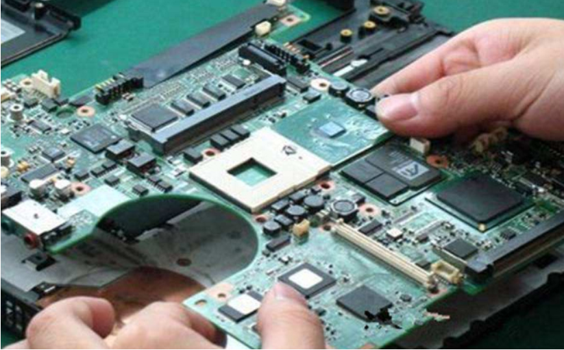
This is particularly evident on the computer motherboard. Many computers can not be started or can be started after several years of use. When the chassis is opened, the phenomenon of electrolytic capacitor bulging can often be seen. If the capacitor is removed to measure the capacity, it is found that it is much lower than the actual value.
The life of capacitor is directly related to the ambient temperature. The higher the ambient temperature is, the shorter the life of capacitor is. This rule applies not only to electrolytic capacitors, but also to other capacitors. Therefore, when looking for fault capacitors, we should focus on the capacitors close to the heat source, such as those near the radiator and high-power components. The closer they are, the more likely they are to be damaged.
2. Characteristics and discrimination of resistance damage
It is often seen that many beginners toss and turn on the resistance when repairing the circuit, which is both disassembled and welded. In fact, it is much more repaired. As long as you understand the damage characteristics of the resistance, you don't need to spend much time.
Resistance is the most numerous component in electrical equipment, but it is not the component with the highest damage rate. Open circuit is the most common resistance damage. It is rare for the resistance value to become larger, and it is rare for the resistance value to become smaller. Common types include carbon film resistor, metal film resistor, wire wound resistor and fuse resistor.
The first two types of resistors are the most widely used, and their damage characteristics are: first, the damage rate of low resistance (below 100 Ω) and high resistance (above 100k Ω) is high, and the damage rate of intermediate resistance (such as hundreds of ohms to tens of kiloohms) is rare; Second, when the low resistance resistance is damaged, it is often burnt and blackened, which is easy to find, while when the high resistance resistance is damaged, there is little trace.
Wire wound resistance is generally used for large current limiting, and the resistance value is not large. When the cylindrical wire wound resistance is burnt out, some will be blackened, or the surface will be cracked, and some will have no trace. Cement resistance is a kind of wire wound resistance, which may break when burned out, otherwise there is no visible trace. When the fuse resistor is burnt out, some surfaces will blow off a piece of skin, and some have no traces, but they will never be burnt and blackened. According to the above characteristics, we can focus on checking the resistance and quickly find out the damaged resistance.
According to the characteristics listed above, we can first observe whether the low resistance resistance on the circuit board has any signs of burning black. Then, according to the characteristics of most open circuits or large resistance values when the resistance is damaged and the high resistance resistance is easy to be damaged, we can use a multimeter to directly measure the resistance at both ends of the high resistance resistance on the circuit board. If the measured resistance value is larger than the nominal resistance value, The resistance must be damaged (it should be noted that the conclusion can be made only after the resistance value is stable, because there may be a charging and discharging process for parallel capacitor elements in the circuit). If the measured resistance value is smaller than the nominal resistance value, it is generally ignored. In this way, each resistance on the circuit board is measured once. Even if you "kill" 1000 by mistake, you will not miss one.
3. Judgment method of operational amplifier
It is difficult for quite a number of electronic maintainers to judge whether the operational amplifier is good or not. I would like to discuss it with you here and hope it will be helpful to you.
The ideal operational amplifier has the characteristics of "virtual short" and "virtual break", which are very useful for analyzing the operational amplifier circuit of linear application. In order to ensure the linear application, the operational amplifier must work in a closed loop (negative feedback). If there is no negative feedback, the op amp under open-loop amplification becomes a comparator. If you want to judge whether the device is good or bad, you should first distinguish whether the device is used as an amplifier or a comparator in the circuit.
4. A trick to test SMT components with multimeter
Some SMD components are very small, which makes it inconvenient to test and repair with an ordinary multimeter probe. First, it is easy to cause short circuit. Second, it is inconvenient for the circuit board coated with insulating coating to contact the metal part of the component pin. Here is a simple method, which will bring a lot of convenience to the detection.
Take two sewing needles of the smallest size, (deep industrial control maintenance technology column) and close them to the multimeter probe, then take a thin copper wire in a multi strand cable, use the thin copper wire to bind the probe and the sewing needle together, and then solder them firmly. In this way, when measuring SMT components with a stylus with a small tip, there is no risk of short circuit. In addition, the tip can puncture the insulation coating, directly hit key parts, and no longer bother to scratch the film.
5. Troubleshooting method for short circuit of public power supply of PCB
During circuit board maintenance, if there is a short circuit in the public power supply, it is often a big problem. Because many devices share the same power supply, each device using this power supply is suspected of short circuit. If there are not many components on the board, the short circuit point can be found by using the "hoe earth" method. If there are too many components, whether the "hoe earth" can hoe to the situation depends on luck. A more effective method is recommended here. With this method, you can get twice the result with half the effort and often find the fault point quickly.
There should be a power supply with adjustable voltage and current. The voltage is 0-30V, and the current is 0-3A. This power supply is inexpensive, about 300 yuan. Adjust the open circuit voltage to the power supply voltage level of the device. First, adjust the current to the minimum. Apply this voltage to the power supply voltage point of the circuit, such as the 5V and 0V terminals of 74 series chips. Slowly increase the current depending on the degree of short circuit. Touch the device with your hand. When you feel that a device is obviously hot, this is often a damaged component. You can take it down for further measurement and confirmation. Of course, during operation, the voltage must not exceed the working voltage of the device, and the connection must not be reversed, otherwise other good devices will be burned.
6. A small rubber to solve big problems
More and more boards are used in industrial control, and many of them are inserted into the slots with gold fingers Due to the harsh environment of the industrial site and the dusty, humid and corrosive gas environment, it is easy to cause the board to have a bad contact fault. Many friends may solve the problem by replacing the board, but the cost of purchasing the board is very considerable, especially for some imported equipment. In fact, you might as well use an eraser to repeatedly wipe the golden finger, clean up the dirt on the golden finger, and try the machine again. Maybe it will solve the problem! The method is simple and practical.
7. Analysis of electrical faults of good and bad
In terms of probability, the electrical faults of good and bad times generally include the following situations:
1) . Poor contact
Poor contact between the board and slot, no connection when the cable is broken, poor contact between the cable plug and terminal block, and faulty soldering of components are all included in this category;
2) . Signal is disturbed
For digital circuits, under specific conditions, faults will appear. It is possible that the control system is indeed affected by too much interference, and the parameters of individual components or the overall performance parameters of the circuit board have changed, making the anti-interference ability tend to the critical point, thus causing faults;
3) Poor thermal stability of components
From a large number of maintenance practices, the thermal stability of electrolytic capacitor is poor, followed by other capacitors, triodes, diodes, ICs, resistors, etc;
4) There is moisture and dust on PCB.
Moisture and dust will conduct electricity with resistance effect, and the resistance value will change in the process of thermal expansion and cold contraction. This resistance value has a parallel effect with other components. If this effect is strong, the circuit parameters will be changed, causing faults;
5) Software is also a consideration
Many parameters in the circuit are adjusted by software. The margin of some parameters is adjusted too low, which is in the critical range. When the operating condition of the machine meets the reason for the software to judge the failure, the alarm will appear.
8. How to quickly find component data
Modern electronic products are various, and there are more and more components. In the field of circuit board welding and maintenance, especially in the field of industrial circuit board maintenance, many components have never been seen or even heard of. In addition, even if the data of components in a certain type of board is complete, it is necessary to read and analyze these data one by one in the computer. If there is no quick search method, the maintenance efficiency will be greatly reduced, In the field of industrial electronic maintenance, efficiency is money.


Just upload Gerber files, BOM files and design files, and the KINGFORD team will provide a complete quotation within 24h.