
Professional PCB manufacturing and assembly
Building 6, Zone 3, Yuekang Road,Bao'an District, Shenzhen, China
+86-13410863085Mon.-Sat.08:00-20:00


Finished product testing of integrated circuit chips
1. Chip introduction
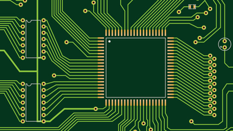
74HC138 is a three-channel input, eight-channel output decoder. The 74HC138 decoder accepts 3-bit binary code inputs (A0, A1 and A2). 74HC138 has 3 enable terminals: Eˉ1 and Eˉ2 are active at low level, and E3 is active at high level. If the decoder wants to have decoding function, Eˉ1 and Eˉ2 must be at low level and E3 must be at high level, otherwise the chip will not With decoding function, the pin distribution is shown in Figure 1, the pin function. When the chip has a decoding function, the output terminals Yˉ0~Yˉ7 output 8 mutually exclusive low-level active outputs. Pin Distribution Table 174HC138 Pin Introduction Pin No. 1-34-67, 9-15816 Pin Name A0-A2Eˉ1, Eˉ2, E3Yˉ7, Yˉ6-Yˉ0GNDVDD Function Description Data Input Enable Control Data Output Logic Ground Logic Power 74HC138 Chip Use When the energy terminals Eˉ1, Eˉ2 and E3 are invalid, that is, the chip does not have the decoding function, and the output terminals are all high level at this time.
2. Test equipment and scheme
2.1 Test equipment
FT test is a chip-level test, which is to establish an electrical connection between the automated test equipment (ATE) and the packaged chip through the test board (Loadboard) and the test socket (Socket). The hardware required for FT testing mainly includes host computer, test machine (ATE), test load board, test socket (socket), chip-loading DUT board, automatic sorter (Handler) and supporting fixture (ChangeKit). Complete electrical connectivity test, functional test and parameter test through FT test software. The program will perform chip screening according to the test result Pass or Fail, that is to say, the pass and fail chips are physically divided into different containers. This test adopts the LK8810S integrated circuit development and application technology platform (hereinafter referred to as "LK8810S technology platform"), which adopts modular and industrial design as a whole. Combined with digital-analog hybrid measurement technology, it supports the testing of common digital and analog chips and related circuits.
2.2 Test plan
In order to screen out failed chips as soon as possible to shorten the overall test time, improve economic benefits, and at the same time ensure the quality and reliability of the screened chips, an open-short test and a functional test are required. The open and short circuit test is mainly to test whether there is any connection error between the wires after the chip is packaged, and whether the metal wire and the substrate are disconnected; the main purpose of the functional test is to verify whether the chip can complete the expected work or function of the design.
2.2.1 Open-short test scheme The core of a chip is the wafer packaged inside the chip. The wafer is connected to the pins outside the chip through connecting wires. However, accidents may occur during the production process, resulting in short-circuiting of the connecting wires or Open circuit phenomenon, so the open and short circuit test should be carried out before the chip leaves the factory. The test principle is to use the Kelvin test principle to test the voltage of the pin by adding an appropriate small current to the chip pin. Mainly test whether each pin of the chip has a short circuit to ground or an open circuit. As shown in the test plan, there is a pair of ESD anti-static protection diodes on the chip pins. During the test, it is judged whether the pins are normal by observing whether the diodes play a role in clamping the voltage. Connect the chip pins through the testing machine, connect the VDD terminal to ground or 0V, connect the GND terminal to the ground, connect a device pin to the PMU unit, and then input or draw 100μA current at the chip pin to detect the voltage of the pin. If the absolute value of the obtained voltage is greater than 1.2V, the pin is considered to be open circuit; if the absolute value of the measured voltage is less than 0.3V, the pin is considered to be short circuited. Applied module Applied current measurement module Measuring voltage PMUDUT100μA secondary tube connected to power supply DUT pin 100μA secondary tube connected to power supply GT+1.2VLT+0.3VPMU Test criterion Open circuit passed short circuit Figure 2 Open short circuit test scheme
2.2.2 Functional test plan
Functional testing is used to test whether the device can complete the preset work or function. The most important thing about a chip is its function, and the design company has restricted its function and determined some of its features and characteristics during the design. In the process of testing, it is necessary to see whether the function of the chip meets the expected working requirements after it is produced. There are many common testing methods, using static functional testing methods, using test vectors or truth tables to detect whether the circuit meets the design requirements. The test vector is the logic value of the input pin and the output pin. When the functional test is being executed, the test system will provide input signals to the input pins of the device under test according to the content provided by the test vector.
And obtain the output logic value on the output pin, and then use the comparison circuit to compare with the content of the test vector. If it matches the expected value, the judgment is correct (Pass), otherwise it is invalid (Fail). Test vectors, usually use 0 and 1 to represent the logic values of input and output pins. At present, most test systems not only use 0 and 1 to represent the logic value of the output pin or input pin, but also English letters. For example, H can represent a high level as a logic 1, and L can represent a low level as a logic 0. Analog chip testing is a little different. Analog chips are subject to the influence of external circuits, or require some special signal input, so the testing methods of analog chips will be more complicated, while digital chips are usually relatively simple.
Static function test commonly used truth table test method is to change the input signal and then measure the output signal to verify whether its function is normal and determine whether the chip is a good product. The function of 74HC138 is to translate the input binary code into a signal and output a low-level signal at the corresponding output terminal. The terminal endows the logic voltage of the function table to read and display the voltage value of the output pin, and compares it with the comparison voltage to judge whether the logic value conforms to the function table. If it matches, the logic function is normal at this time, otherwise it is an error. If the number of judging pins is greater than 8, the functional test ends. Start the for loop to determine the pin i=1; i<9; i++ enable terminal, input logic voltage at the input terminal, read the voltage of the pin to be tested, and the upper computer displays the pin number and voltage value to determine whether the pin conforms to the chip pin of the function table The function is normal, the chip pin function error jumps out of the loop, and ends the test NNYY function test plan
3. Test hardware circuit design
3.1 Test board interface assignment
The LK8810 test system is mainly composed of five parts: analog function board (WM), power supply and measurement board (PM), digital function pin board (PE), interface and reference voltage board (IV), special test and analog switch board (CS) , where the digital function pin board is the core of the test machine to realize the digital function test, and it can complete the PMU test of the pin by cooperating with the power supply and the measurement board. Before the test, according to the characteristics of the chip 74HC138 to be tested, the interface assignment of the test board is designed according to Table 3, and the cycle test program can be used during the test. During the test, the enabling terminal should not be connected to an active level in advance, otherwise the open-short circuit test cannot be completed. Figure 4 Breadboard Test Circuit Figure 5DUT Board Test Circuit Table 374HC138 Test Board Wiring Table Module Name Test Machine Port IO Pin Control Pin Module Name 74HC138 Test Board
3.2 Circuit Construction
A breadboard is used to complete the construction of the test hardware environment. As shown in the breadboard test circuit, the circuit is connected and tested through the DuPont line and the SCSI conversion interface line according to the distribution of the test board interface. The breadboard test circuit can be disassembled and assembled flexibly, without additional board making and soldering work. The DUT board test method is shown in Figure 5. The DUT board design is based on the premise of carefully studying the chip technical manual, and the DUT board circuit is designed according to the distribution of the test board interface. When designing, first determine the interface form of the test machine resources, and then determine the chip test interface, which usually includes Noguchi socket, double-row pins, adapter blocks, etc., and then design the test peripherals according to different chip requirements. When connecting the DUT board, you must pay attention to the assignment of the pins. Once the connection is wrong, it may cause irreversible damage to the tester.
Light-emitting diodes and their basic circuits
May 31,2023


Just upload Gerber files, BOM files and design files, and the KINGFORD team will provide a complete quotation within 24h.